
Connector

a technology of connecting rods and connecting rods, applied in the direction of couplings/cases, coupling device connections, electrical devices, etc., can solve the problem that the opening lid cannot be properly accommodated in the routing space, and achieve the effect of excellent space efficiency

Active Publication Date: 2021-02-02
SUMITOMO WIRING SYST LTD
View PDF12 Cites 0 Cited by
  • Summary
  • Abstract
  • Description
  • Claims
  • Application Information

AI Technical Summary

Benefits of technology

[0008]A sealing member may be disposed in the lid for sealing the connection surface at the closed position, and the side surface of the second housing may include an outer peripheral wall surrounding the sealing member when the lid is at the open position. The outer peripheral wall prevents damage to the sealing member when the lid is open. As a result, the liquid-tightness of the sealing member between the closed lid and the connection surface is ensured.
[0009]The second housing may include a second housing body and a wire cover to be mounted on the second housing body. The side surface and the outer peripheral wall may be provided on the wire cover. According to this configuration, the outer peripheral wall need not be provided on the second housing body and the structure of the second housing body can be simplified.
[0011]The connector of this disclosure provides with excellent space efficiency.

Problems solved by technology

However, if the projecting direction of the lid does not coincide with a routing direction of a mating wiring harness and a routing space of the mating wiring harness is limited, the opened lid may not be accommodated properly in the routing space.

Method used


Image

  • Connector
  • Connector
  • Connector

Examples


Embodiment Construction

[0021]A specific example of the connector of this disclosure is described below with reference to the drawings. Note that the invention is not limited to these illustrations and is intended to be represented by claims and include all changes in the scope of claims and in the meaning and scope of equivalents.

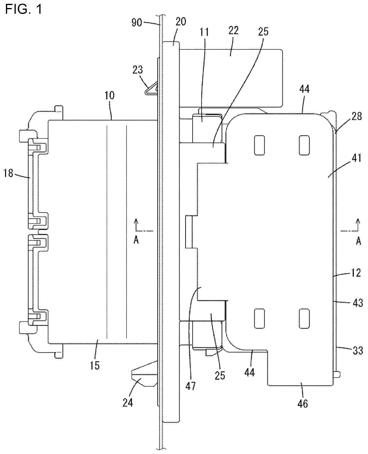
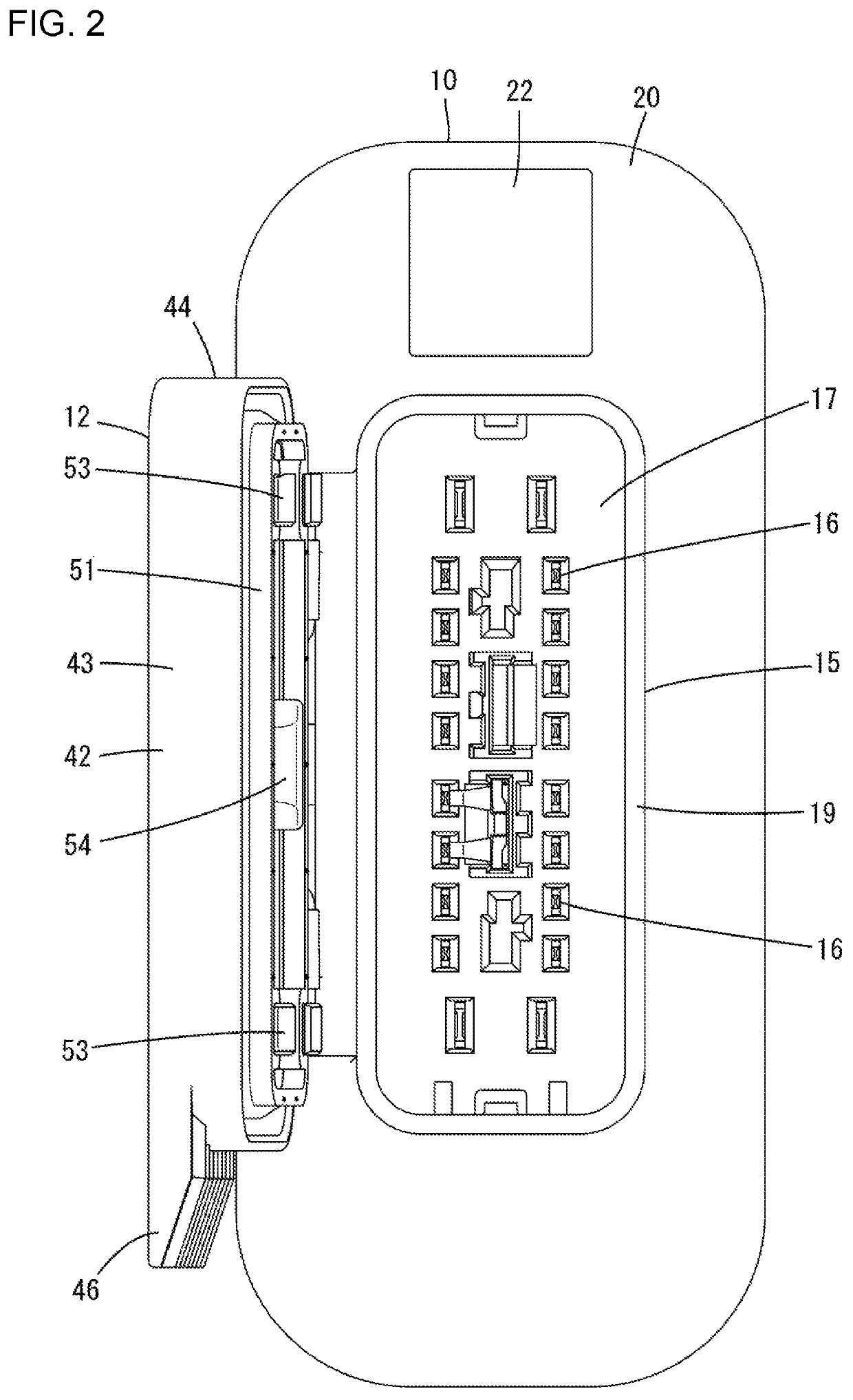
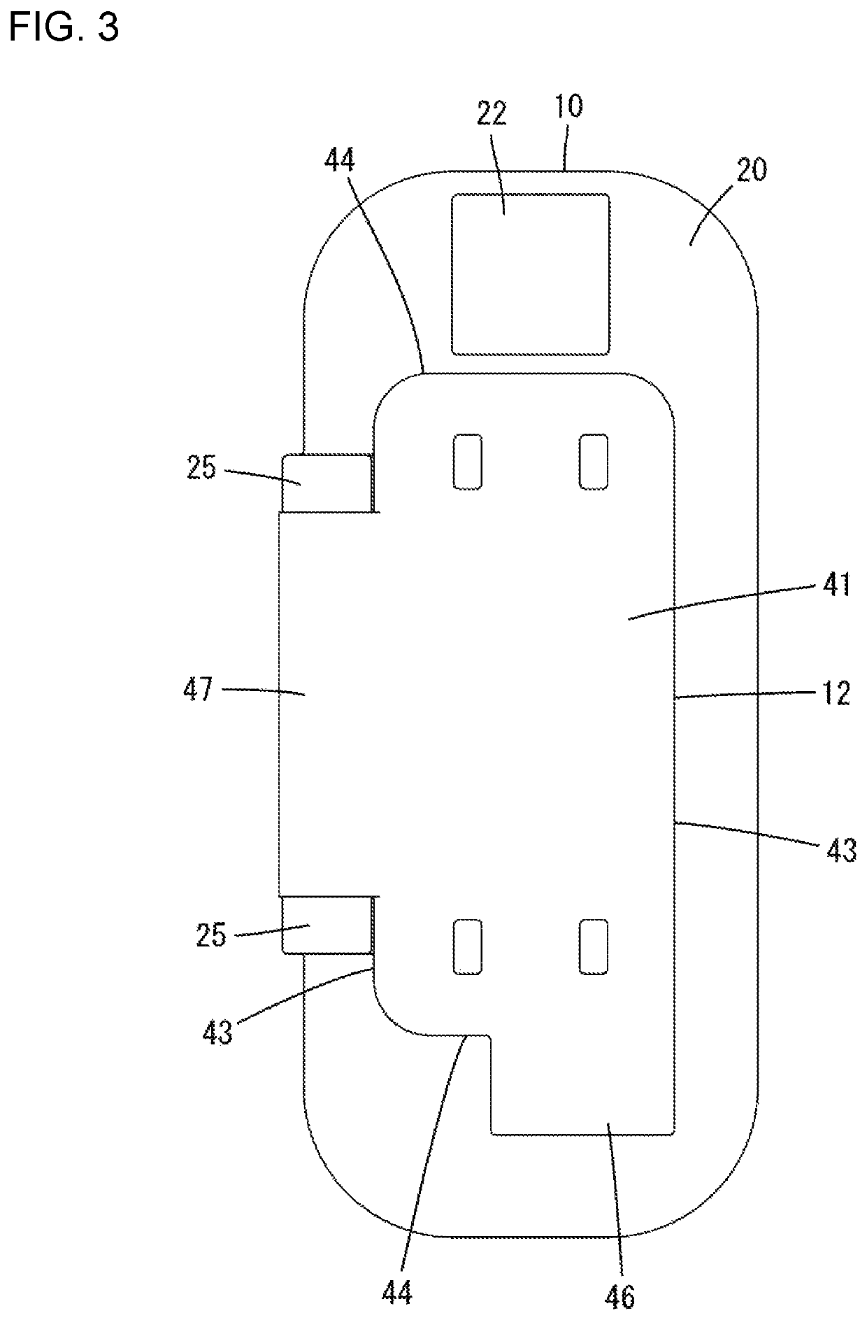
[0022]A connector according to an embodiment is mounted on a panel 90 such as a door panel of an unillustrated automotive vehicle. For example, a front surface side (left side of FIG. 1) of the panel 90 is a vehicle body side, and a rear surface side (right side of FIG. 1) of the panel 90 is a door side. The connector includes a first housing 10 and a second housing 11 connectable to each other. A lid 12 is supported on the first housing 10, and a biasing member 14 and a sealing member 13 (see FIG. 8) are disposed in the lid 12. The first housing 10, the second housing 11 and the lid 12 are made of synthetic resin. The biasing member 14 is a winding spring (torsional coil spring)...


PUM


Abstract

A first housing includes a wide connection surface and a bearing formed on an edge on one side along the longitudinal direction of the connection surface. A second housing includes a side surface formed to face in a direction intersecting a connecting direction of the first and second housings. A lid is displaceable about a shaft supported by the bearing portion to a closed position where the lid covers the connection surface and an open position where the lid member contacts the side surface. The lid is biased from the open position to the closed position by a biasing member. An outer shape of the lid has a long side arranged along the longitudinal direction of the connection surface and a short side intersecting the long side and shorter than the long side.

Description

BACKGROUNDField of the Invention[0001]The disclosure relates to a connector.Related Art[0002]Japanese Unexamined Patent Publication No. 2004-39332 discloses a connector for towing vehicle. The connector is used in an automotive wiring harness for electrically connecting an object to be towed and a vehicle body. This connector includes a housing with an opening into which a connector of a wiring harness on the side of the object to be towed is inserted. A lid for closing the opening is mounted rotatably on the upper end of the opening of the housing. The lid has a rotary shaft on an end part and is biased in a direction to close the opening by a winding spring wound on the outer periphery of the rotary shaft.[0003]Japanese Unexamined Patent Publication No. 2013-155825 discloses a technique for closing an opening of a socket body by a lid port. Japanese Unexamined Patent Publication No. H07-29635 discloses a lid provided on a vehicle-side connector of an electric vehicle.[0004]A proje...

Claims


Application Information

Patent Timeline
Patent Type & Authority Patents(United States)
IPC IPC(8): H01R13/52H01R13/50
CPCH01R13/5213H01R13/501H01R13/5202H01R13/502H01R2201/26
Inventor KOSAKA, RYOTAROIMAI, YUJIROSAITO, SHOKAWAMOTO, MASAMI
Owner SUMITOMO WIRING SYST LTD
Learn More