
All-around spherical light field rendering method

a spherical light field and rendering method technology, applied in the field of computer graphics, can solve the problems of requiring repeated calculations, requiring a lot of human resources to produce rendering data, and falling short of expectations of artificial rendering results, so as to save computing resources, improve results, and quickly and instantly see

Active Publication Date: 2021-02-02
PLEX VR DIGITAL TECH SHANGHAI CO LTD
View PDF8 Cites 0 Cited by
  • Summary
  • Abstract
  • Description
  • Claims
  • Application Information

AI Technical Summary

Benefits of technology

The present invention allows users to quickly and easily see the results of a rendering process using their mobile phones or laptops. The interface allows users to interact with the rendering engine to view the object from different angles, resulting in better results in fields such as shopping. The rendering results are based on real picture data, making them more authentic and immersive for users. Overall, the invention saves computing resources and provides a more efficient and effective user experience.

Problems solved by technology

However, with the development of virtual reality technology, such artificial rendering results have fallen short of expectations because of a lack of realism.
First, it takes a lot of human resources to produce rendering data, specifically a modeler needs to spend a lot of time on building a model similar to a real object, and debugging materials and textures of the model to make it look close to a real object. This process may require repeated calculation.
Second, the rendering results are significantly different from real objects, since the 3D models and texture maps input by traditional rendering engines are handmade, many details of the objects cannot be retained. These details are the best expression of an authenticity of the objects, so there is always a big difference between a rendered image and an image seen by naked eyes.

Method used


Image

  • All-around spherical light field rendering method
  • All-around spherical light field rendering method
  • All-around spherical light field rendering method

Examples


Embodiment Construction

[0028]The present invention will be further described with reference to the drawings.

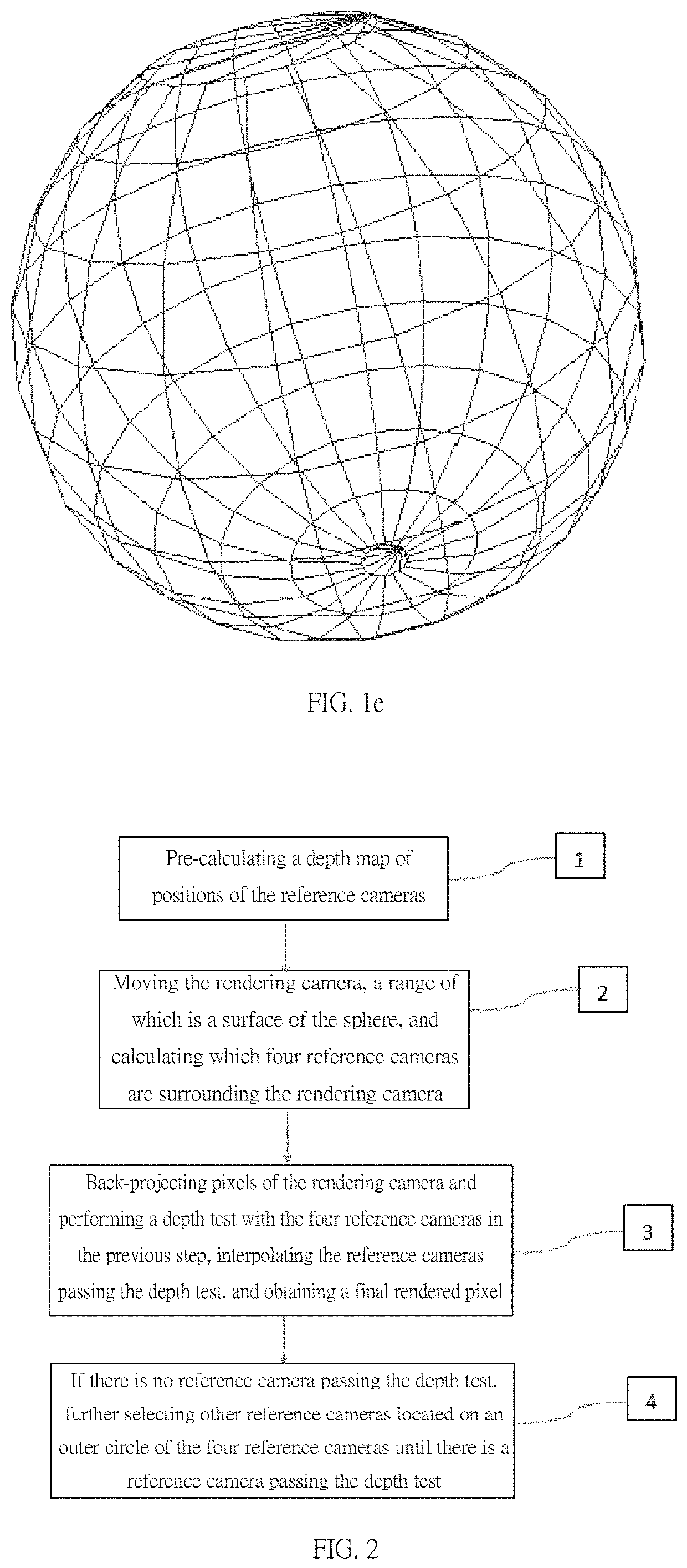
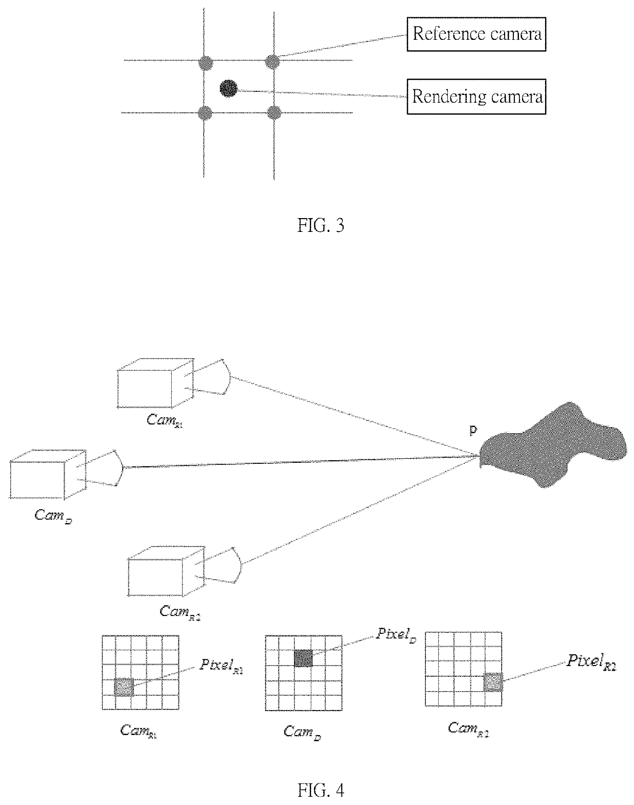
[0029]Referring to FIG. 1a to FIG. 4, FIG. 1a to FIG. 4 show an embodiment of the present invention. This embodiment implements a light field rendering engine using a non-traditional method, which can not only realize real-time rendering, but also render images of real objects from various perspectives by using multi-viewpoint images. Specific implementation steps are as follows:

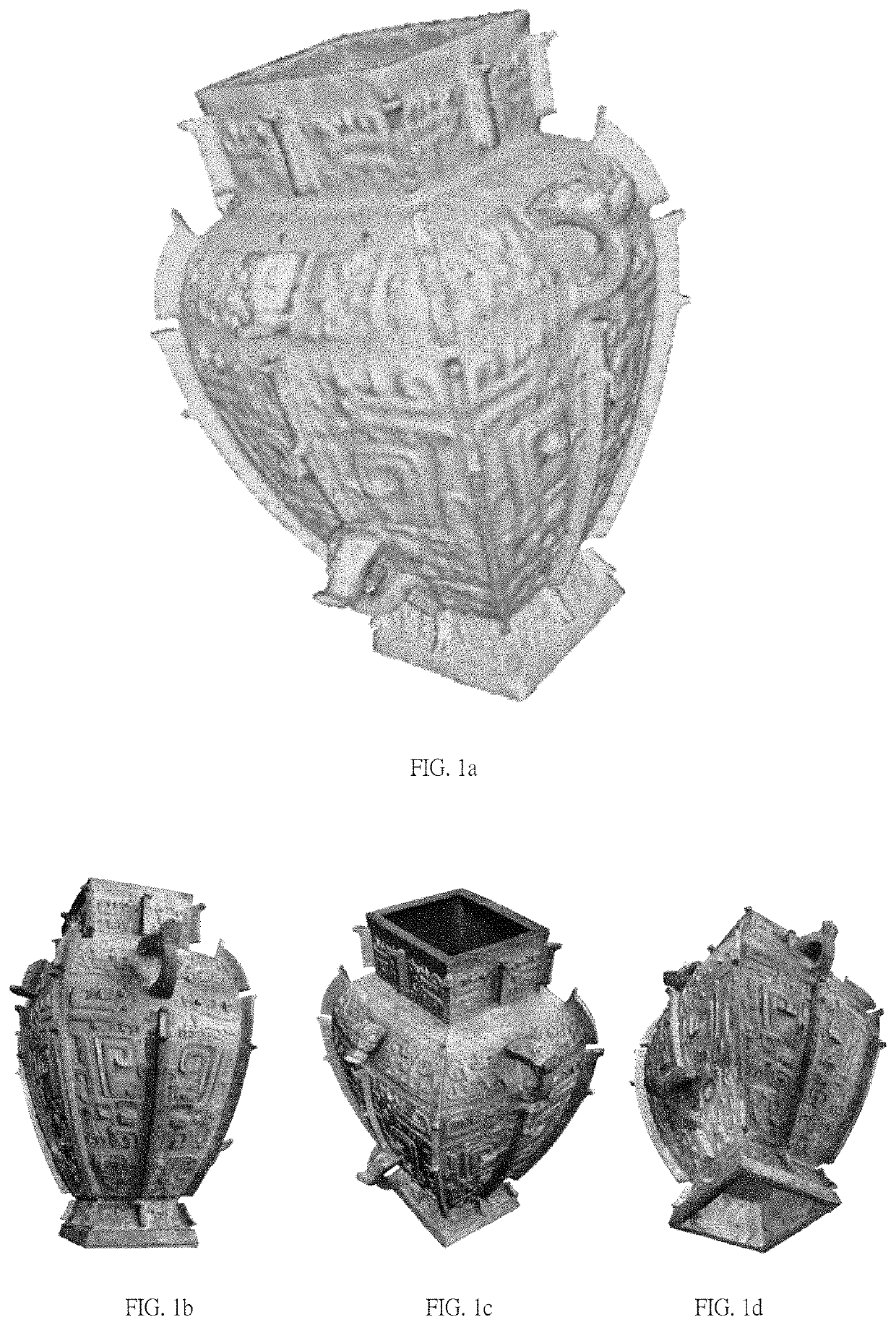
[0030]FIG. 1a to FIG. 1d are input format pictures of data registration format of this embodiment. The input data of this embodiment includes: a low-precision three-dimensional object model (30,000 to 100,000 faces), 200 to 300 external and internal parameters of the reference cameras, a same number of pictures, files describing a relative position relationship of the reference cameras, and setting files describing attributes of a data set thereof. Please refer to the diagrams for specific information.

[0031]Referring to FIG....


PUM


Abstract

The present invention relates to an all-around spherical light field rendering method, comprising: a preparation step, i.e., preparing to input and load related files; pre-computing a latticed depth map of positions of reference cameras which are densely covered on a sphere; moving a rendering camera, enabling the moving range of the rendering camera to be the surface of the sphere, and calculating and identifying the reference cameras surrounding the rendering camera around the rendering camera; performing back projection on pixels of the rendering camera, and performing depth test with the four reference cameras; and interpolating the reference cameras passing through the depth test, thereby obtaining a finally rendered pixel value. By means of the present invention, the rendering results can be rapidly seen in real time; an object can be observed from any angle on the spherical surface, and a real immersion feeling can be felt.

Description

BACKGROUND OF THE INVENTION1. Field of the Invention[0001]The invention relates to a computer graphics technical field, and more particularly, to an all-around spherical light field rendering method capable of real-time rendering real objects by using multi-viewpoint images.2. Description of the Prior Art[0002]Currently, a well-known 3D model rendering engine uses a combination of model and texture mapping, and is rendered into a map by using a rasterized rendering pipeline. Most of characters and scenes in a current game field are rendered by this method. However, with the development of virtual reality technology, such artificial rendering results have fallen short of expectations because of a lack of realism.[0003]The current rendering engine mainly has the following two problems:[0004]First, it takes a lot of human resources to produce rendering data, specifically a modeler needs to spend a lot of time on building a model similar to a real object, and debugging materials and tex...

Claims


Application Information

Patent Timeline
Patent Type & Authority Patents(United States)
IPC IPC(8): G06T15/50G06T7/557
CPCG06T15/506G06T7/557G06T2207/10028G06T2215/16G06T3/40G06T15/50G06T15/205G06T7/50
Inventor YU, JINGYIYU, HUANGJIE
Owner PLEX VR DIGITAL TECH SHANGHAI CO LTD
Learn More