
Encoder signal processing device, printer, printer-equipped imaging apparatus, and encoder signal processing method

a technology of encoder signal and encoder, which is applied in the field of encoder signal processing devices, printers, printer-equipped imaging apparatuses, etc., can solve the problems of not output (lost, lost pulse signal cannot be detected)

Active Publication Date: 2021-01-26
FUJIFILM CORP
View PDF16 Cites 0 Cited by
  • Summary
  • Abstract
  • Description
  • Claims
  • Application Information

AI Technical Summary

Benefits of technology

[0009]The present invention is conceived in view of such matters. An object of the present invention is to provide an encoder signal processing device, a printer, a printer-equipped imaging apparatus, and an encoder signal processing method that can remove the effect of a noise signal mixed with an encoder signal and favorably deal with a case where an original pulse signal is lost from the encoder signal.
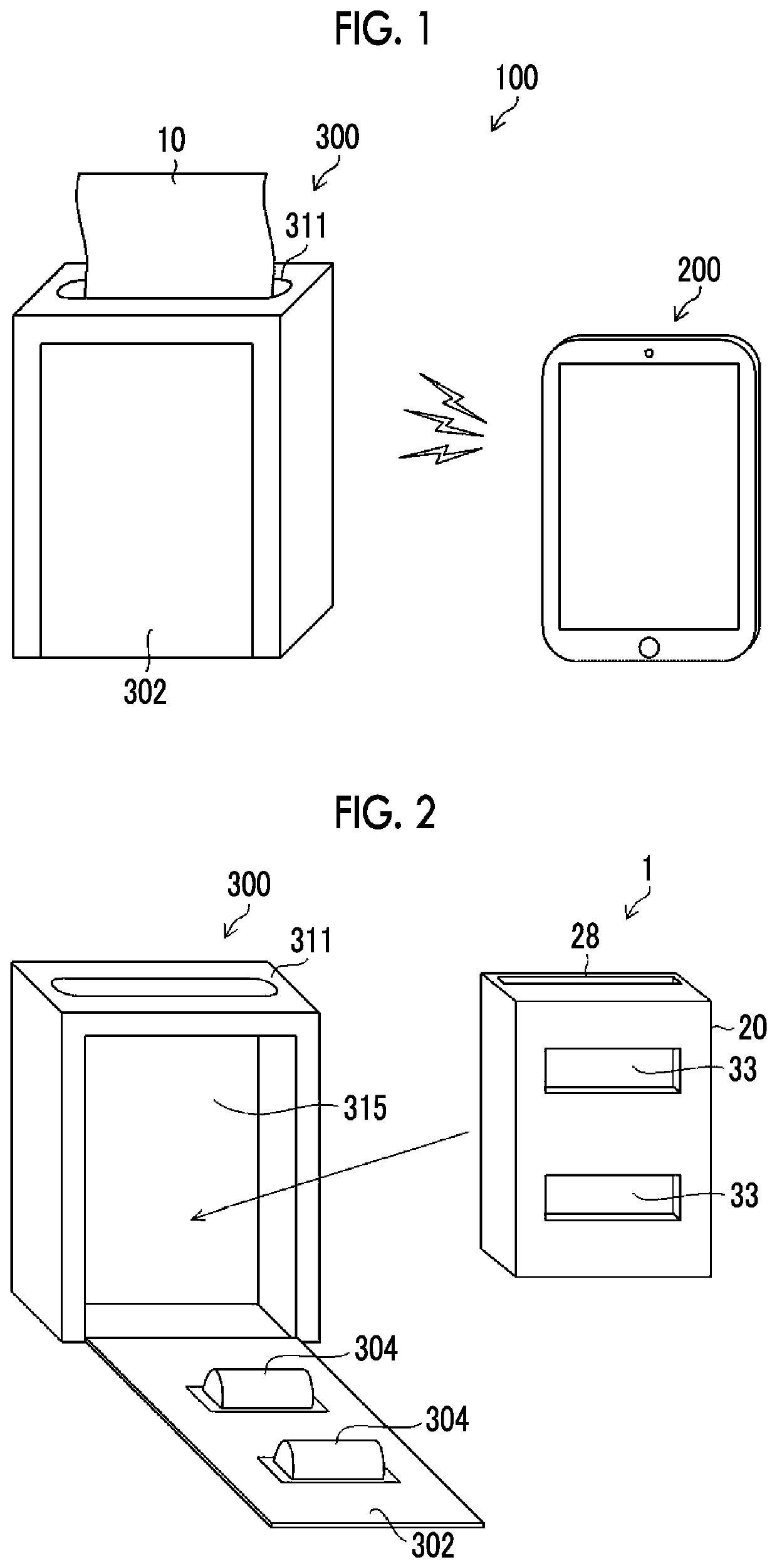
[0018]A printer according to still another aspect of the present invention comprises the encoder signal processing device, an image data input unit that inputs image data, a line head that is driven based on the input image data, a transport unit that transports a printing medium as the transported body in a direction orthogonal to a longitudinal direction of the line head, the encoder that outputs the encoder signal including a pulse signal having a cycle corresponding to a transport speed of the printing medium transported by the transport unit, and a control unit that controls a printing timing of the line head for a line image in synchronization with the pulse signal detected by the pulse signal detection unit and the pulse signal generated by the pulse signal generation unit. In a case where the line head is driven in synchronization with the pulse signal and the noise signal, white streaks accompanied by mixing of the noise signal occur in the printing medium. However, by removing the noise signal, the occurrence of white streaks can be prevented. In addition, in a case where the pulse signal is lost, black streaks occur in the printing medium. However, since the pulse signal is generated in a case where the pulse signal is lost, black streaks can be removed.
[0025]According to the present invention, the effect of the noise signal mixed with the encoder signal can be removed, and it is possible to favorably deal with a case where the original pulse signal is lost from the encoder signal.

Problems solved by technology

In this case, a problem arises in that the pulse signal (rectangular wave signal) corresponding to the slit to which dust is attached is not output (lost) from the encoder.
While the device disclosed in JP2003-148997A can remove the noise signal mixed with the encoder signal, a problem arises in that the lost pulse signal cannot be detected in a case where the original pulse signal to be included in the encoder signal is lost by attachment of dust or the like.

Method used


Image

  • Encoder signal processing device, printer, printer-equipped imaging apparatus, and encoder signal processing method
  • Encoder signal processing device, printer, printer-equipped imaging apparatus, and encoder signal processing method
  • Encoder signal processing device, printer, printer-equipped imaging apparatus, and encoder signal processing method

Examples


first embodiment

[0112]FIG. 13 is a block diagram illustrating the encoder signal processing device 52 (FIG. 9) disposed in the printer 300.

[0113]As illustrated in FIG. 13, the encoder signal processing device 52 is mainly configured with an encoder signal input unit 521, a pulse signal detection unit 522, an effective detection period setting unit 523, a pulse signal generation unit 524, and a pulse signal combining unit 525. The encoder signal processing device 52 may be configured with a digital circuit or may be configured with one or a plurality of central processing units (CPU) in the printer 300, software for processing the encoder signal, and the like.

[0114]The rotary encoder 36 outputs the encoder signal that includes the pulse signal having a cycle corresponding to the rotational speed (the transport speed of the instant film 10) of the rotating slit plate 37 (capstan roller 35). As described above, 200 slits 37a (FIG. 6) are formed around the rotating slit plate 37 in the present example....


PUM

PropertyMeasurementUnit
widthaaaaaaaaaa
slit widthaaaaaaaaaa

Abstract

An encoder signal processing device, a printer, a printer-equipped imaging apparatus, and an encoder signal processing method that can remove the effect of a noise signal mixed with an encoder signal and favorably deal with a case where an original pulse signal is lost from the encoder signal are provided. An effective detection period setting unit 523 sets an effective detection period for detecting a subsequent pulse signal, each time a pulse signal detection unit 522 detects a pulse signal from an encoder signal. The pulse signal detection unit 522 detects the pulse signal only within the set effective detection period. In a case where the pulse signal detection unit 522 does not detect the pulse signal within the effective detection period, a pulse signal generation unit 524 generates the pulse signal after the effective detection period.

Description

CROSS-REFERENCE TO RELATED APPLICATIONS[0001]This application is a Continuation of PCT International Application No. PCT / JP2017 / 007615 filed on Feb. 28, 2017, which claims priority under 35 U.S.C § 119(a) to Japanese Patent Application No. 2016-135047 filed on Jul. 7, 2016. Each of the above application(s) is hereby expressly incorporated by reference, in its entirety, into the present application.BACKGROUND OF THE INVENTION1. Field of the Invention[0002]The present invention relates to an encoder signal processing device, a printer, a printer-equipped imaging apparatus, and an encoder signal processing method and particularly, to a technology for favorably acquiring a pulse signal from an encoder signal output from an encoder.2. Description of the Related Art[0003]Generally, an encoder (optical rotary encoder) is widely used for detecting the amount of rotation or a rotational speed of an electric motor, the amount of movement or a movement speed of a transported body transported b...

Claims


Application Information

Patent Timeline
Patent Type & Authority Patents(United States)
IPC IPC(8): G01D5/244B41J2/45G03B17/50B41J2/21G01D5/347G03C3/00
CPCG01D5/24457B41J2/2135B41J2/2146B41J2/45G01D5/24495G01D5/347G03B17/50G03C3/00
Inventor FUJII, TAKESHIKATSURA, HIROFUMIUCHIYAMA, HIROYUKI
Owner FUJIFILM CORP
Learn More