Flow cytometry apparatus pulling sample stream through observation chamber

a flow cytometer and sample stream technology, applied in the field of flow cytometry, can solve the problems that the conventional high-throughput flow cytometer system must be limited in use, and achieve the effects of reducing fluid carryover, increasing sample throughput rate, and extending the range of assays amenable to high-throughput flow cytometry analysis

Active Publication Date: 2021-01-05
UNM RAINFOREST INNOVATIONS
View PDF44 Cites 0 Cited by
  • Summary
  • Abstract
  • Description
  • Claims
  • Application Information

AI Technical Summary

Benefits of technology

[0008]There is a need for a high-throughput flow cytometry system that minimizes or at least reduces the length of tubing required between the samples and the flow cytometer.
[0011]To eliminate the need for an external peristaltic pump, the present invention directs the use of flow cytometers that do not require positive pressure for sample delivery and pull rather than push the samples through the observation chamber of the cytometer.
[0022]The present invention contemplates a miniaturized plate handling assembly, for instance, an automated XYZ stage as mentioned above, to replace the autosampler used in the conventional HyperCyt® high-throughput flow cytometer system. Alternatively, the conventional autosampler may be adapted to provide the basis of microplate manipulation. The XYZ stage is integrated with a flow cytometer that has a sample intake port that exerts a negative force (suction) on incoming samples. The suction intake port or probe aspirates samples from microplate wells, using its built-in negative-pressure sampling mode. This direct sampling technique can reduce the sample tubing path to less than 10 cm. A flow cytometer system in accordance with the present invention achieves significantly reduced fluid carryover, for instance, to possibly less than 1.0%.
[0023]A high-throughput flow cytometry system in accordance with the present invention greatly increases the sample throughput rate over conventional systems and may require only a single low-cost flow cytometer. The platform enables performance in a wider variety of specialized applications and secondary assays.
[0024]The present invention provides a flow cytometry system that may be used in assays involving viable cells, extending the range of assays amenable to high throughput flow cytometry analysis.

Problems solved by technology

The conventional HyperCyt® high-throughput flow cytometer system must therefore be limited in use to assays insensitive to such physiological perturbations.

Method used


Image

  • Flow cytometry apparatus pulling sample stream through observation chamber
  • Flow cytometry apparatus pulling sample stream through observation chamber
  • Flow cytometry apparatus pulling sample stream through observation chamber

Examples


Embodiment Construction

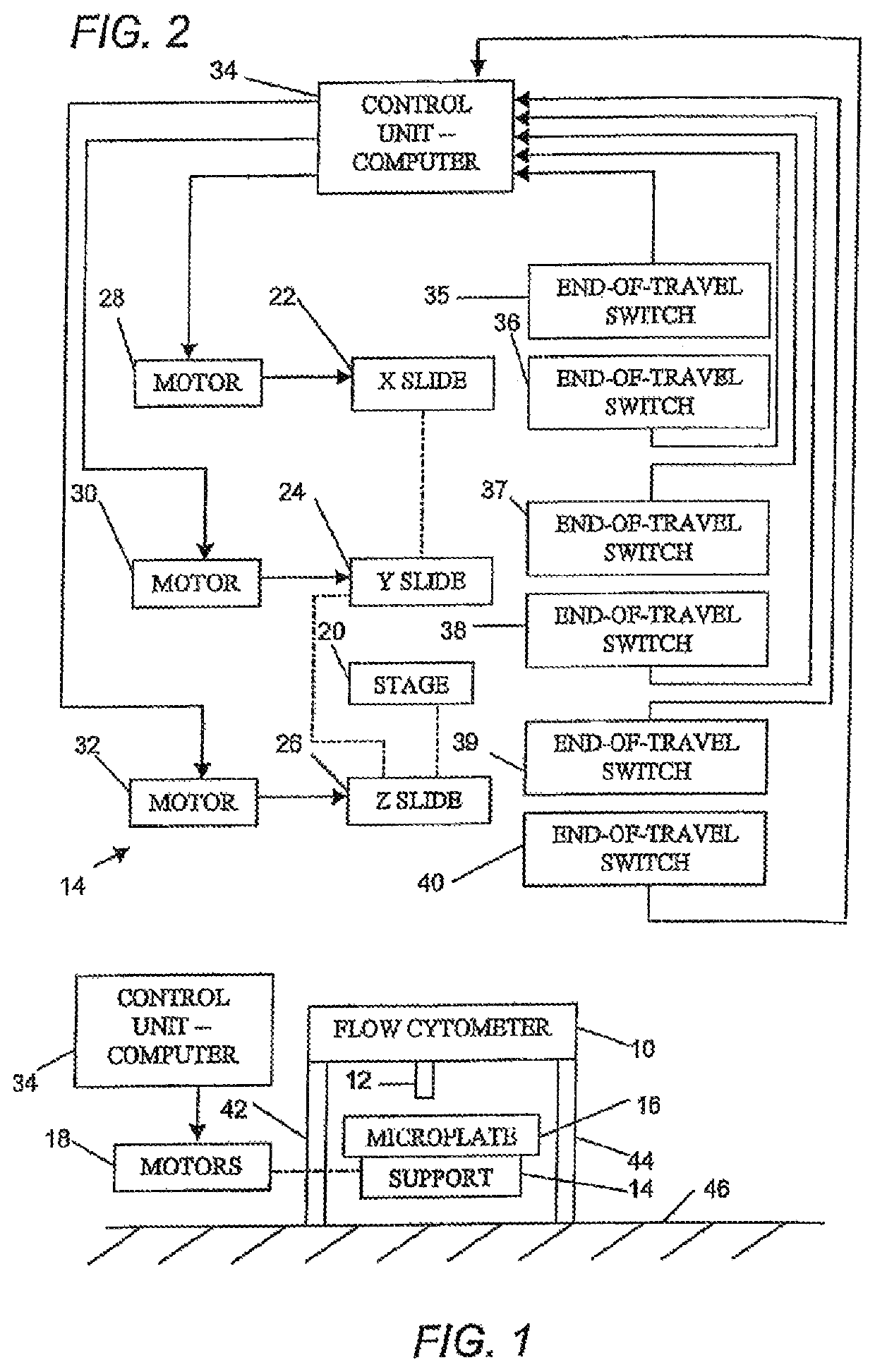
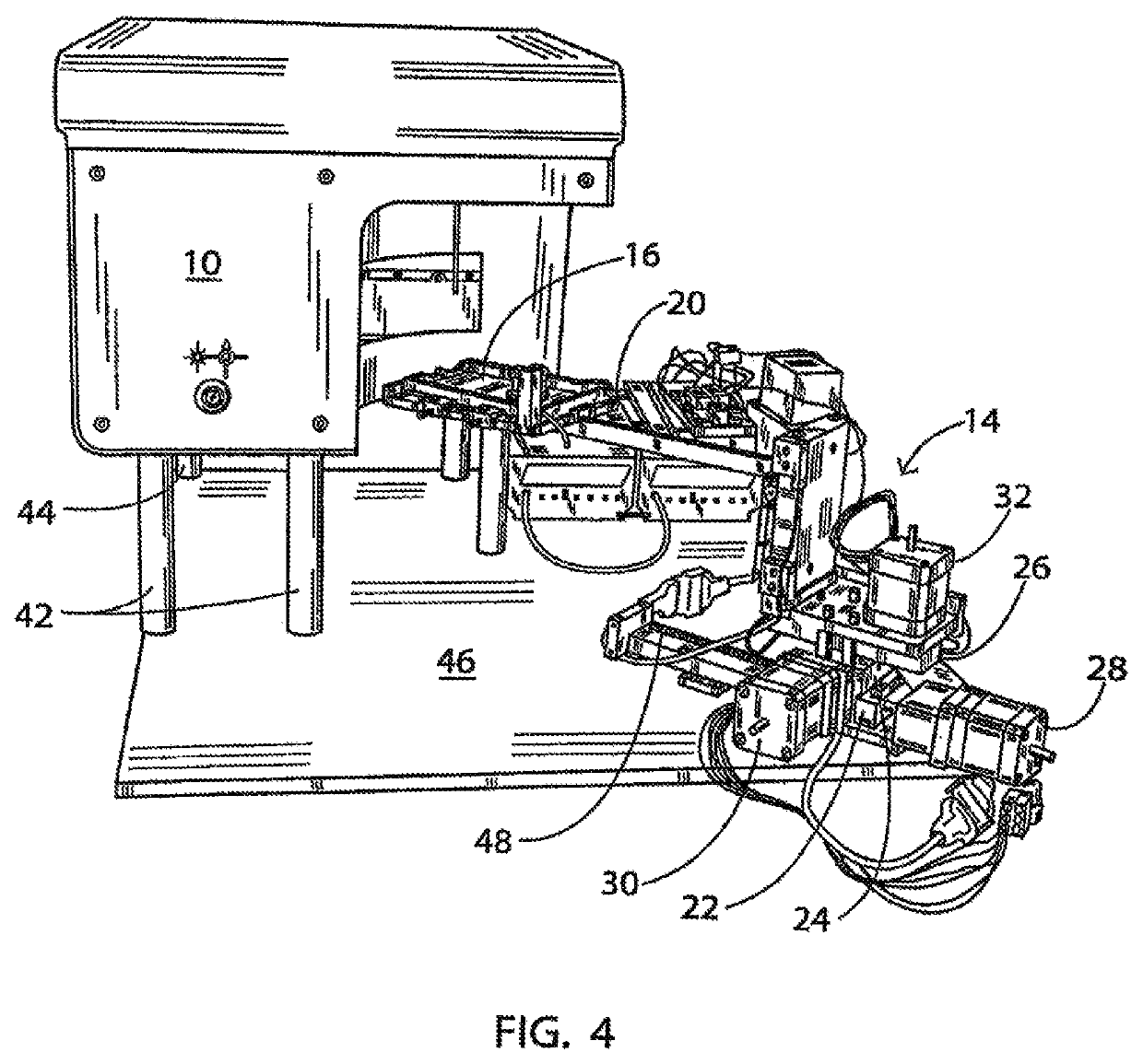
[0030]As depicted in FIG. 1, a flow cytometry apparatus with increased throughput comprises a flow cytometer 10 having a suction intake probe 12, a support 14 for a microplate 16 having a plurality of sample wells, and motive elements 18 operatively connected to at least one of the probe and the support for moving intake probe 12 and support 14 relative to one another so that the intake probe is sequentially aligned with different sample wells of microplate 16. There are no fluid pumping elements between support 14 and flow cytometer 10 so that a bubble-separated sample stream comprising a series of samples from different wells of the microplate is forced to the flow cytometer solely by virtue of a negative pressure communicated via intake probe 12.

[0031]Intake probe 12, support 14, and motive elements 18 cooperate to introduce aliquots of a separation fluid between successive samples from different wells of microplate 16 to generate the bubble-separated sample stream. Flow cytomete...


PUM

PropertyMeasurementUnit
lengthaaaaaaaaaa
volumeaaaaaaaaaa
pressureaaaaaaaaaa

Abstract

A flow cytometry apparatus includes a flow cytometer having a suction or negative-pressure intake probe, a support for a microplate having a plurality of sample wells, and motive elements operatively connected to at least one of the probe and the support for moving the intake probe and the support relative to one another so that the intake probe is sequentially aligned with different sample wells of the microplate. The apparatus has no fluid pumping elements between the support and the flow cytometer so that a bubble-separated sample stream is forced to the flow cytometer solely by virtue of a negative pressure communicated via the intake probe.

Description

CROSS-REFERENCE TO RELATED APPLICATION[0001]This application is a division of application Ser. No. 13 / 717,279 filed Dec. 17, 2012, now U.S. Pat. No. 9,752,964, in turn filed as a division of application Ser. No. 12 / 802,880 filed 16 Jun. 2010 and claims the benefit of U.S. Provisional Patent Application No. 61 / 269,265 filed 22 Jun. 2009.GOVERNMENT INTEREST STATEMENT[0002]This invention is made with government support under contract number R01 HG005066 NIH and contract number U54 MH074425 NIH. The government has certain rights in this invention.BACKGROUND OF THE INVENTION[0003]This invention relates to flow cytometry.[0004]Flow cytometers are frequently used for the analysis of particles such as cells or beads in a number of different applications. The system allows for determination of both particle morphology and evaluation of particle features by detection of optical labels. The ability to distinguish multiple particles sizes and colors allows multiplex application providing higher...

Claims


Application Information

Patent Timeline
Patent Type & Authority Patents(United States)
IPC IPC(8): G01N21/00G01N15/06G01N33/00G01N35/08G01N1/14
CPCG01N35/08G01N1/14Y10T436/118339G01N15/1459G01N35/109
Inventor EDWARDS, BRUCE S.SKLAR, LARRY A.SALESKY, RONALD D.
Owner UNM RAINFOREST INNOVATIONS
Why Eureka
Try Eureka