
DC-DC controller with DCM control

a controller and dcm technology, applied in the field of dc-dc controllers, can solve the problems of increasing the overall power consumption of the dc-dc conversion circuit b>900, and achieve the effect of reducing the switching loss of the output stag

Active Publication Date: 2020-12-29
UPI SEMICON CORP
View PDF12 Cites 0 Cited by
  • Summary
  • Abstract
  • Description
  • Claims
  • Application Information

AI Technical Summary

Benefits of technology

[0005]Accordingly, the invention provides a dc-dc controller, which can effectively reduce the switching loss of the output stage of the dc-dc conversion circuit.
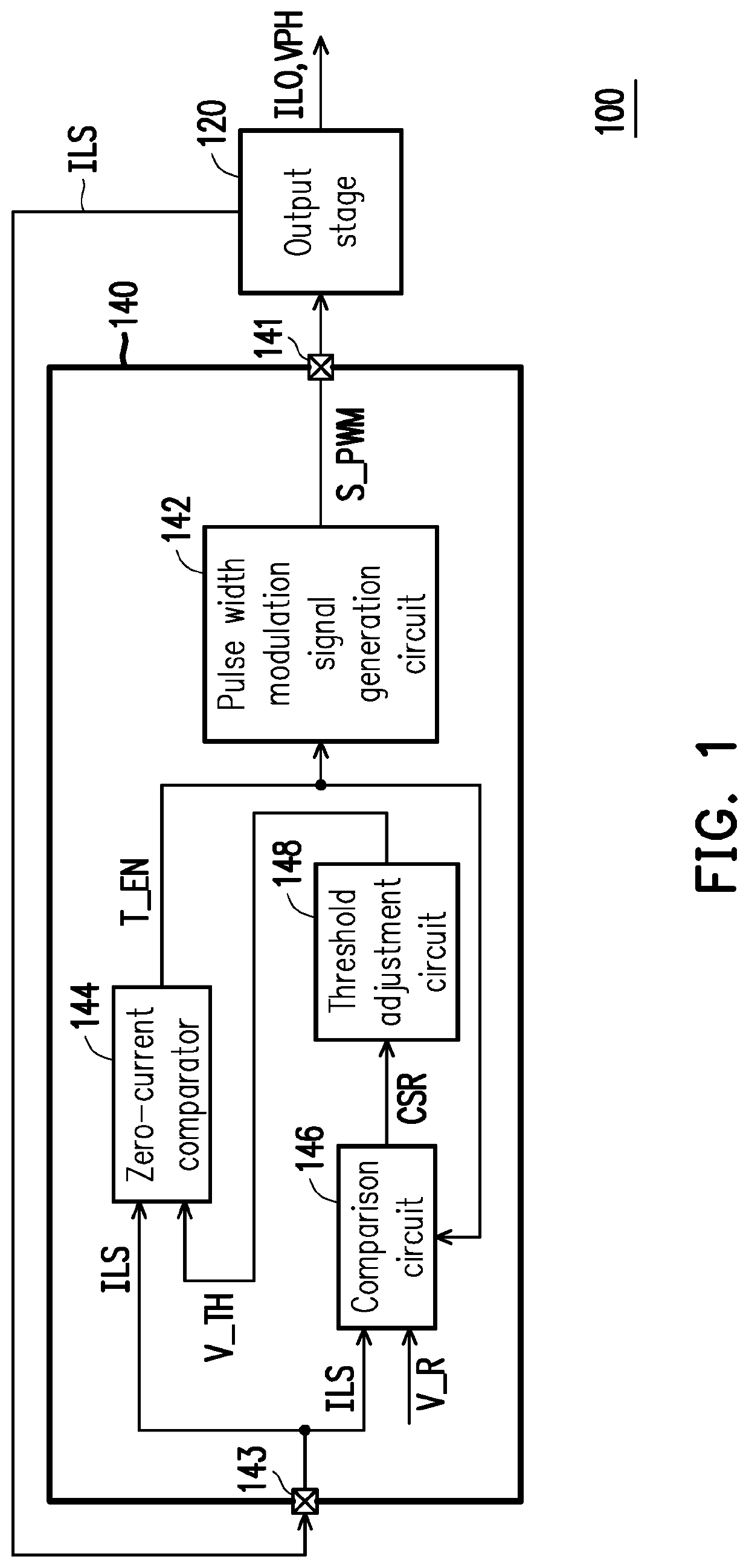
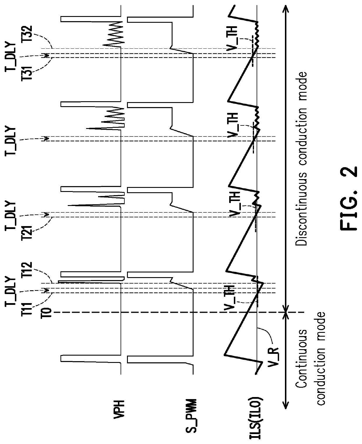
[0012]Based on the above, the dc-dc controller proposed by the invention may adjust the first preset value according to the sensing signal related to the output current of the output stage, so the output stage can be switched to the turn off state at the same time when the output current drops to zero to prevent the output current form becoming negative current. As a result, the purpose of zero current switching can be achieved, thereby reducing the switching loss of the output stage.

Problems solved by technology

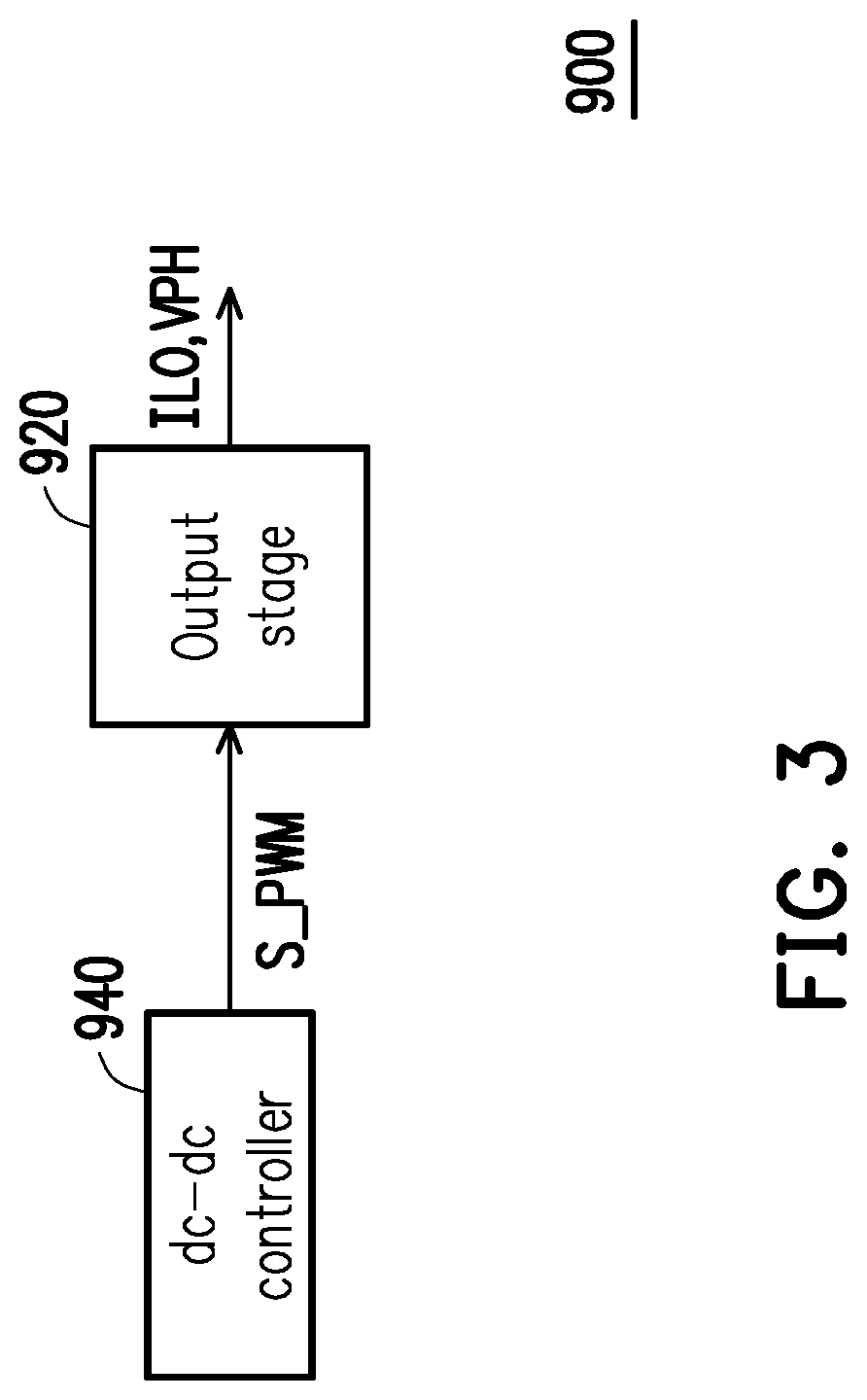
Consequently, the output stage 920 will suffer a switching loss, thereby increasing the overall power consumption of the dc-dc conversion circuit 900.

Method used


Image

  • DC-DC controller with DCM control
  • DC-DC controller with DCM control
  • DC-DC controller with DCM control

Examples


Embodiment Construction

[0018]Descriptions of the invention are given with reference to the exemplary embodiments illustrated with accompanied drawings, in which same or similar parts are denoted with same reference numerals. In addition, identical or similar reference numbers stand for identical or similar elements in the figures and the embodiments.

[0019]With reference to FIG. 1, FIG. 1 illustrates a circuit block diagram of a dc-dc conversion circuit 100 according to an embodiment of the invention. The dc-dc conversion circuit 100 may include a dc-dc controller 140 and an output stage 120. The dc-dc controller 140 is coupled to the output stage 120, and configured to control the output voltage 120 to generate and provide an output voltage VPH and an output current ILO.

[0020]The dc-dc controller 140 includes a pulse-width modulation output pin 141, a pulse width modulation signal generation circuit 142, a current sensing pin 143, a zero-current comparator 144, a comparison circuit 146 and a threshold adj...


PUM


Abstract

A dc-dc controller is provided. The dc-dc controller includes a current sensing pin, a zero-current comparator, a comparison circuit and a threshold adjustment circuit. The current sensing pin is coupled to an output stage to receive a current sensing signal related to the output current. The zero-current comparator is coupled to the current sensing pin, and receives the current sensing signal and a first preset value to provide a zero-current signal. The comparison circuit is coupled to the zero-current comparator and the current sensing pin, and compares the current sensing signal with a second preset value to provide an adjustment signal. The threshold adjustment circuit is coupled to the comparison circuit and the zero-current comparator, and generates the first preset value according to the adjustment signal.

Description

CROSS REFERENCE TO RELATED APPLICATION[0001]This application claims the priority benefit of China application serial no. 201810471536.X, filed on May 17, 2018. The entirety of the above-mentioned patent application is hereby incorporated by reference herein and made a part of specification.BACKGROUND OF THE INVENTION1. Field of the Invention[0002]The invention relates to a power conversion control technique, and more particularly, relates to a dc-dc controller.2. Description of Related Art[0003]FIG. 3 is a circuit block diagram of a dc-dc conversion circuit in conventional art. With reference to FIG. 3, a dc-dc conversion circuit 900 includes a dc-dc controller 940 and an output stage 920. The dc-dc controller 940 is configured to generate a pulse width modulation signal S_PWM for controlling the output stage 920 to generate an output voltage VPH and an output current ILO. In general, the dc-dc conversion circuit 900 at light loading will enter a discontinuous conduction mode (DCM) ...

Claims


Application Information

Patent Timeline
Patent Type & Authority Patents(United States)
IPC IPC(8): H02M3/04H02M1/00
CPCH02M1/00H02M3/04H02M2001/0048H02M2001/0025H02M2001/0009H02M1/083H02M1/0058H02M3/08Y02B70/10H02M1/0025H02M1/0054H02M1/0009H02M1/0048
Inventor CHANG, CHIH-LIENLAI, MIN-RUI
Owner UPI SEMICON CORP
Learn More