
Sealing joint for low pressure pipe systems and method of manufacture

a technology of low pressure pipe and sealing joint, which is applied in the direction of non-disconnectible pipe joints, sewer pipelines, mechanical devices, etc., can solve the problems of difficult installation of solvent weld systems, chemical solvents or cements, and difficult tasks, and achieves greater relative length

Active Publication Date: 2020-12-29
S & B TECHN PRODS
View PDF17 Cites 2 Cited by
  • Summary
  • Abstract
  • Description
  • Claims
  • Application Information

AI Technical Summary

Benefits of technology

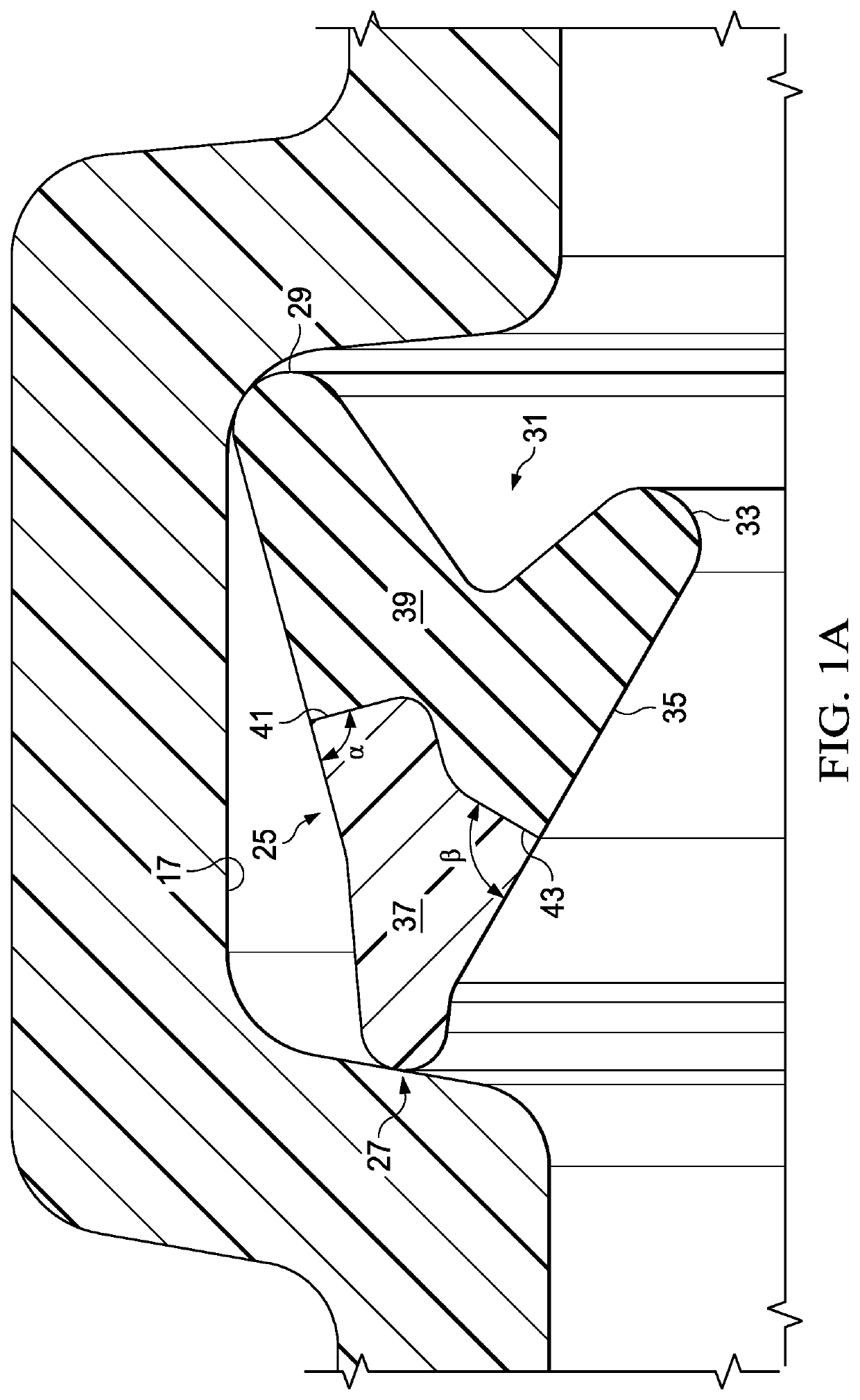
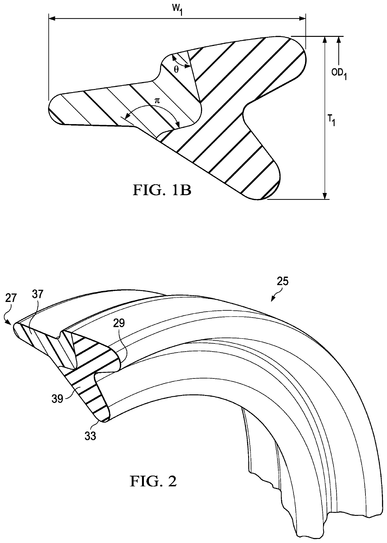
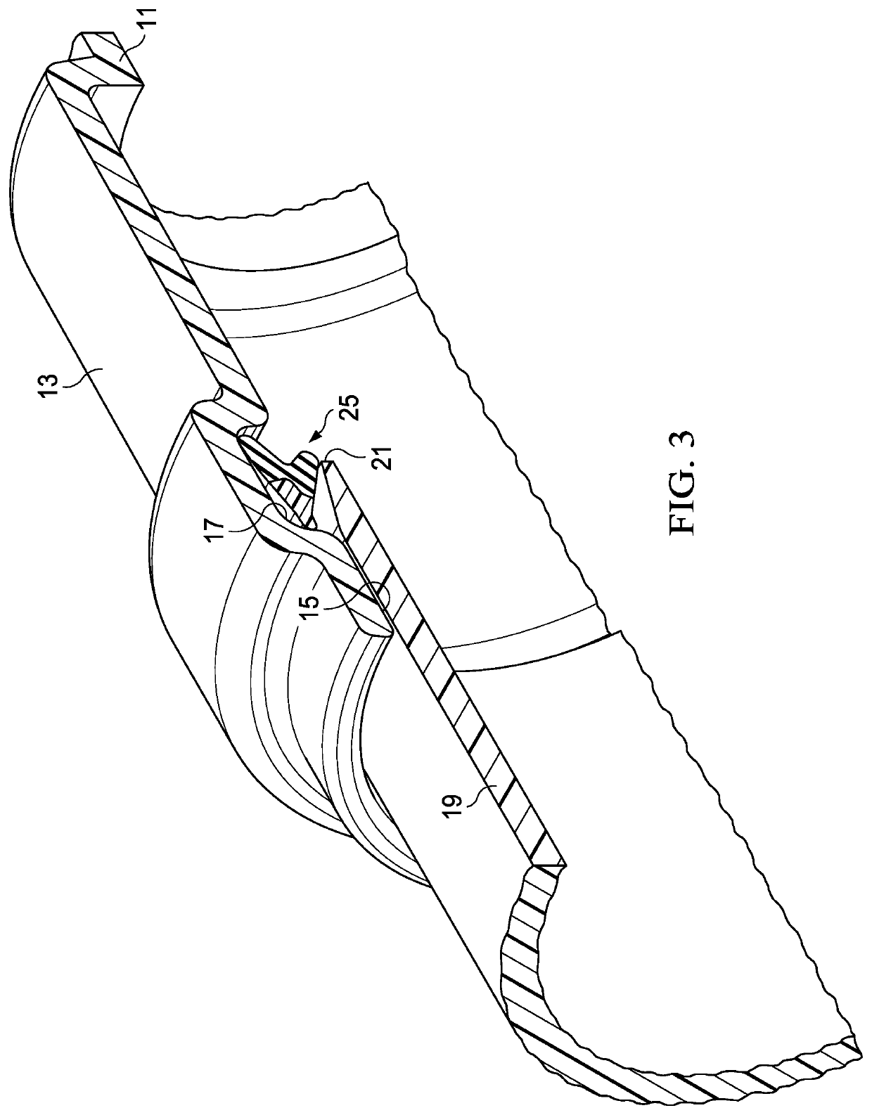
The invention is a sealed joint for low pressure pipe, such as drain waste vent and sewer pipe. The joint is made using a composite gasket made of hard plastic and flexible thermoplastic elastomer material. The gasket is placed between the ends of the two sections of low pressure pipe and sealed using a sealing process called "pushing". The hard plastic portion of the gasket is formed using injection molding, while the flexible thermoplastic elastomer material is formed through a second mold. The sealed joint creates a tight connection between the two sections of low pressure pipe, preventing leaks and fishmouthing during joint make up.

Problems solved by technology

However, solvent weld systems are sometimes more difficult to install for inexperienced installers and installation conditions may make the use of mechanical couplings preferable.
This can be a difficult task when an installer is unaware of the particular conditions they might encounter during an installation.
The use of chemical solvents or cements can cause various complications because of potential toxicity of the chemicals.
The installer might then encounter an instance in which the use of glue fittings creates a safety risk, such as in a confined space where ventilation of the glue vapors is not sufficient to prevent inhalation by the installer or combustion of the vapors by contact with a flame or other ignition source is a possibility.
Additionally, the prior art procedures often required several steps or operations, and often certain regulated safety precautions came into play that took time to complete.

Method used


Image

  • Sealing joint for low pressure pipe systems and method of manufacture
  • Sealing joint for low pressure pipe systems and method of manufacture
  • Sealing joint for low pressure pipe systems and method of manufacture

Examples


Embodiment Construction

[0031]The invention described herein and the various features and advantageous details thereof are explained more fully with reference to the non-limiting examples which are illustrated in the accompanying drawing and detailed in the following description. Descriptions of well-known components and processes and manufacturing techniques are omitted so as to not unnecessarily obscure the workings of the invention. The examples used herein are intended merely to facilitate an understanding of ways in which the invention herein may be practiced and to further enable those of skill in the art to practice the invention. Accordingly, the examples should not be construed as limiting the scope of the claimed invention.

[0032]The sealing gasket of the invention is used to make up a sealed joint between mating sections of low pressure pipe, such as Drain Waste Vent (DWV) pipe or sewer pipe and has properties specifically designed for that application. The primary application will be described w...


PUM

PropertyMeasurementUnit
angleaaaaaaaaaa
anglesaaaaaaaaaa
pressureaaaaaaaaaa

Abstract

A method and sealing gasket are shown for providing a sealing joint between a spigot section and a socket section of low pressure plastic pipe, such as drain waste vent pipe that require a minimum of tools and operational steps to complete. The sealing gasket is installed in one of the sections to be joined and the spigot section is inserted within a mouth opening of the socket section with the sections being pressed together in a single operation, thereby forming both the joint and the seal. The sealing gasket is a composite gasket made with one section of a hard plastic material and one section of a thermoplastic elastomer material. No glue or adhesive is required.

Description

CROSS REFERENCE TO RELATED APPLICATIONS[0001]The present application claims priority from a previously filed provisional application, Ser. No. 62 / 463,029, filed Feb. 24, 2017, entitled “Sealing Joint For Low Pressure Pipe Systems and Method of Manufacture”, by the same inventor.BACKGROUND OF THE INVENTION2. Field of the Invention[0002]The present invention generally relates to sealing structures and methods for low pressure pipe sealing applications and, more specifically, for such seal structures particularly adapted for use in pipe joints formed using drain waste vent pipe and sewer pipe.3. Background of the Invention and Description of the Prior Art[0003]A number of low pressure plastic pipe systems are in commercial use at the present time. Common examples include sewer pipe and Drain Waste Vent pipe. Drain Waste Vent (DWV) pipe is typically used to convey waste water from residential and commercial buildings via sewer and grey water lines. In such applications, the flow is gene...

Claims


Application Information

Patent Timeline
Patent Type & Authority Patents(United States)
IPC IPC(8): F16L55/178E03C1/122F16L17/035F16L21/03F16J15/08F16L17/025F16L21/00E03F3/04F16L13/02F16L21/035B29C45/14
CPCF16L17/035F16L21/005E03C1/122F16L55/178F16J15/0818F16L21/03E03F3/04F16L13/0236F16L17/025F16L21/035B29C2045/14959F16J2015/0875
Inventor QUESADA, GUIDO
Owner S & B TECHN PRODS
Learn More