Stiff guide wire with anchoring configuration

a guide wire and configuration technology, applied in the direction of guide wires, osteosynthesis devices, catheters, etc., can solve the problems of immediate risk of perforation or other damage to sensitive organs or tissues, significant delay in the procedure, adversely affecting the outcome of the procedure,

Active Publication Date: 2020-12-29
SEASPINE
View PDF3 Cites 0 Cited by
  • Summary
  • Abstract
  • Description
  • Claims
  • Application Information

AI Technical Summary

Problems solved by technology

Accidental displacement of the guide wire during a procedure, when immediately noticed, leads to significant delay in the procedure while the placement procedure is repeated.
Such displacement may adversely affect the outcome of a procedure, and in some cases, poses an immediate risk of perforation or other damage to sensitive organs or tissues.
In some cases, such as in intervertebral procedures, the tissue into which the guide wire is inserted is soft tissue which does not provide strong retention of the guide wire.
In such applications, there is an increased risk of the guide wire being displaced axially as a result of forces inadvertently transferred to the guide wire during introduction or removal of tools or implants along the wire.
In all such cases, loss of placement of the guide wire during a procedure is a common complication which is at least an inconvenience and cause of delay for the surgeon, and may potentially be dangerous.

Method used


Image

  • Stiff guide wire with anchoring configuration
  • Stiff guide wire with anchoring configuration
  • Stiff guide wire with anchoring configuration

Examples


Embodiment Construction

[0038]The present invention is a stiff guide wire with a selectively deployable anchoring configuration for use in various surgical procedures.

[0039]The principles and operation of guide wires according to the present invention may be better understood with reference to the drawings and the accompanying description.

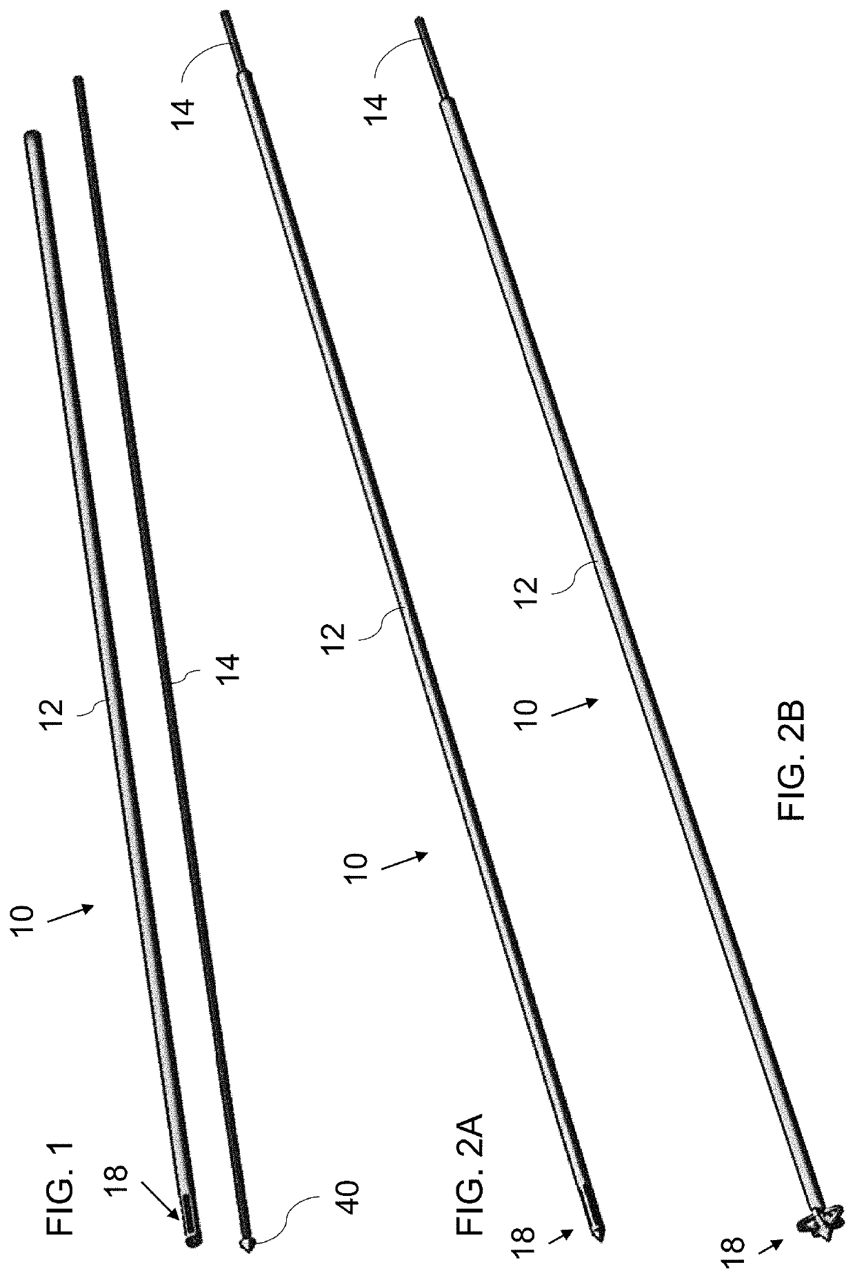
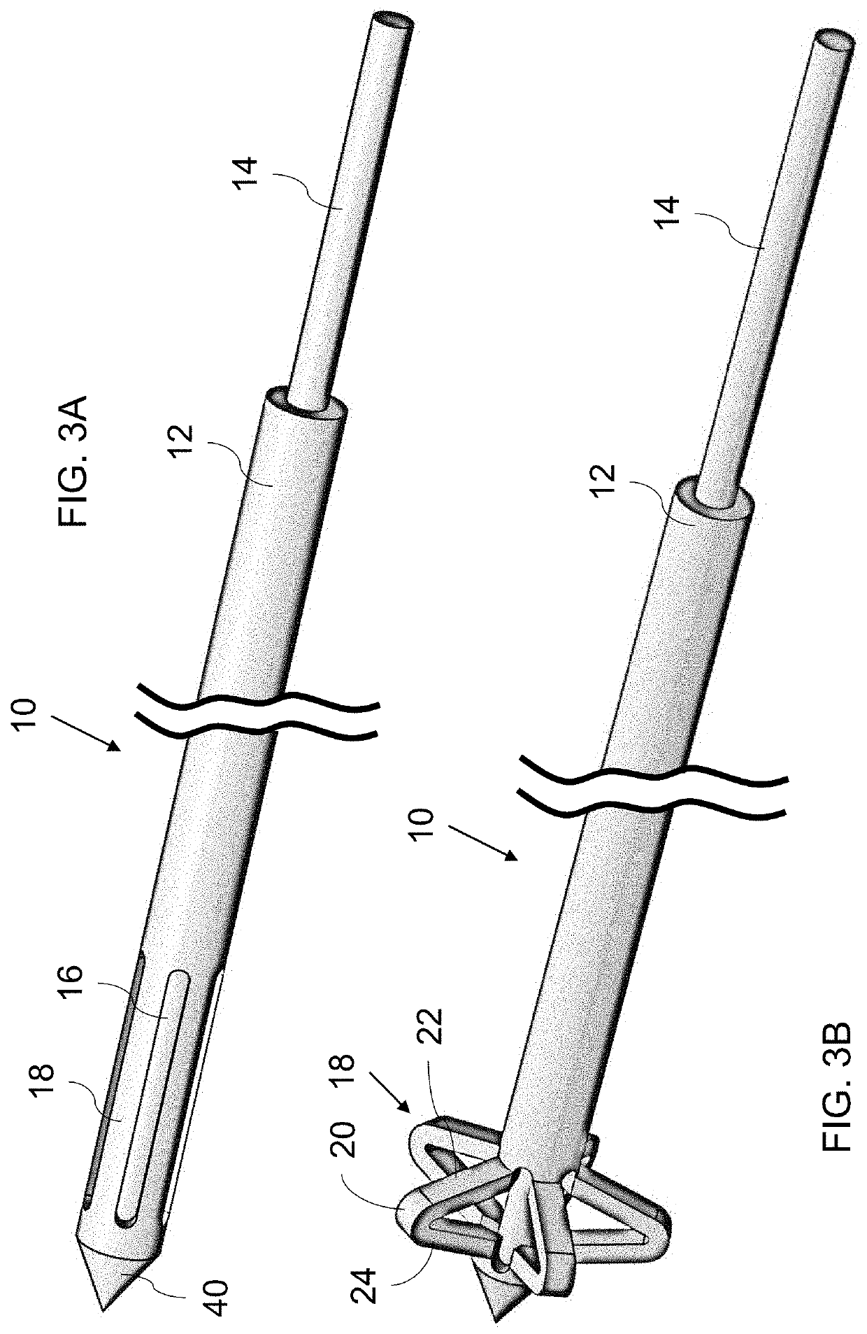
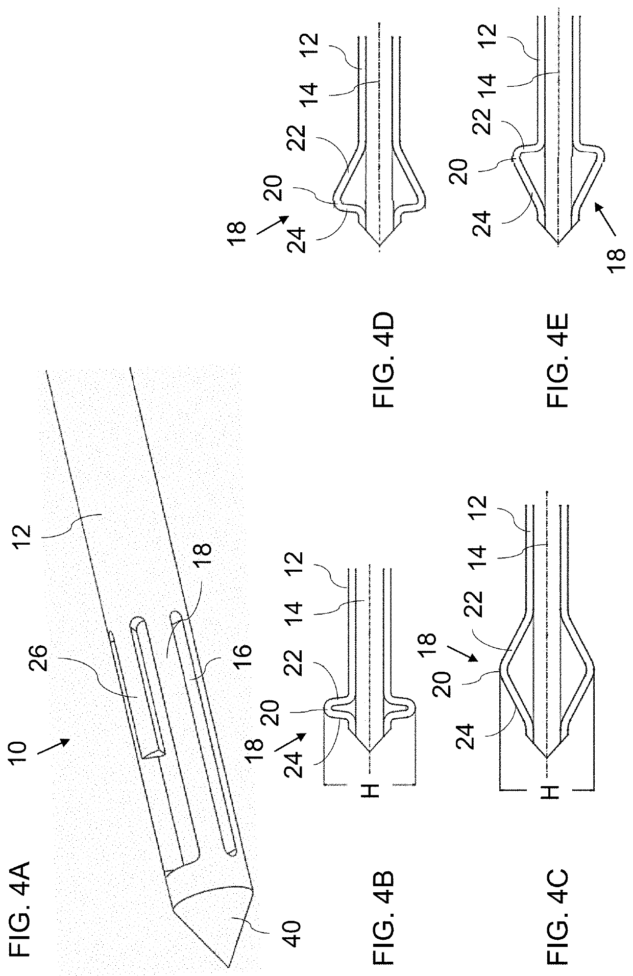
[0040]Referring now to the drawings, FIGS. 1-12 show various implementations of a device 10 which serves as a stiff guide wire for surgical procedures. In general terms, device 10 includes a metal tube 12 having an internal channel, and a metal central rod 14 deployed in close-fitting sliding engagement within tube 12. A distal end of tube 12 is in rigid mechanical engagement, or rigid interconnection, with a distal end of central rod 14. A region of tube 12 is longitudinally slotted (slots 16 best seen in FIGS. 3A, 5A, 7 and 10) to form a plurality of deflectable strips 18 so that advancing of tube 12 relative to central rod 14 causes outward deflection of deflectable st...


PUM


Abstract

A device (10) which serves as a stiff guide wire for surgical procedures includes a tube (12) having an internal channel, and a central rod (14) in close-fitting sliding engagement within the tube. The tips of the tube and the central rod are in rigid mechanical engagement or interconnection. A region of the tube (12) is longitudinally slotted to form deflectable strips (18) so that advancing of the tube (12) relative to central the rod (14) causes outward deflection of the strips (18) to form an anchoring configuration. The central rod (14) and the tube (12) together define a stiff guide wire preferably having a length-to-width ratio in excess of 100:1.

Description

FIELD AND BACKGROUND OF THE INVENTION[0001]The present invention relates to surgical devices and methods and, in particular, it concerns a stiff guide wire with a selectively deployable anchoring configuration for use in various surgical procedures.[0002]In various fields of surgery, such as minimally invasive spinal surgery (MISS), a sequence of steps need to be performed at an accurately defined location within the body which is not directly visible to the surgeon. In order to ensure correct placement of each tool and / or implant that is introduced into the body to perform one of the required steps, a stiff guide wire (referred to as a “Kirschner wire” or “K-wire”) is often used. The guide wire is first introduced and positioned with its end at a target location within the body, typically by use of fluoroscopy or other real-time imaging modalities, and the guide wire is then used as a guide rail for subsequently introduced tools and / or implants, often introduced “over-the-wire” (OT...

Claims


Application Information

Patent Timeline
Patent Type & Authority Patents(United States)
IPC IPC(8): A61M25/09A61B17/88A61M25/04A61B17/84
CPCA61M25/09025A61B17/8852A61B17/8897A61M25/04A61M25/09A61M2025/09125A61B17/844
Inventor LOEBL, ODEDSHARABANI, NETANEL
Owner SEASPINE
Why Eureka
Try Eureka