Adipose tissue separation device and methods

a tissue separation and adipose tissue technology, applied in the direction of biomass after-treatment, suction drainage containers, wound drains, etc., can solve the problems of reducing the likelihood of tissue rejection, and affecting the ability of liposuction to remove tissu

Active Publication Date: 2020-12-29
STRYKER CORP
View PDF11 Cites 0 Cited by
  • Summary
  • Abstract
  • Description
  • Claims
  • Application Information

AI Technical Summary

Benefits of technology

The present patent text describes a tissue separating device that can be used for liposuction surgery. The device includes a canister body with a movable filter mesh assembly separating the interior volume of the canister body into an upper vacuum chamber and a lower vacuum chamber. The filter mesh is adjustable to change its position relative to a tissue harvesting port in the canister body. The device can be connected to a fatty liposuction aspirate source and a collection device for removing pure fat collected on the filter mesh. This makes the process of removing fatty tissue from the body safer and easier.

Problems solved by technology

However, the adipose cells are relatively delicate and the number of steps and length of time required to separate and process the harvested tissue prior to re-introduction into the patient contributes directly to the success of the operation and decreases the likelihood the tissue will be rejected.
However, the nature of liposuction procedures preclude easy tissue isolation after initial harvest, especially on a large scale, because the volume and / or viscosity of the extracted liposuction effluent also contains unwanted components such as oil, blood and anesthetic solution.
Currently, there are no standard techniques, methods, or devices that exist for the simple, large scale isolation and refinement of liposuction-harvested adipose tissue.
Although a number of specialized cannulas, needles and methods for tissue harvest and preparation exist, these techniques are tedious and inefficient.
Known centrifuge-free processes require a large number of steps which result in a cumbersome harvesting and re-injection process that leaves room for much improvement.

Method used


Image

  • Adipose tissue separation device and methods
  • Adipose tissue separation device and methods
  • Adipose tissue separation device and methods

Examples


Embodiment Construction

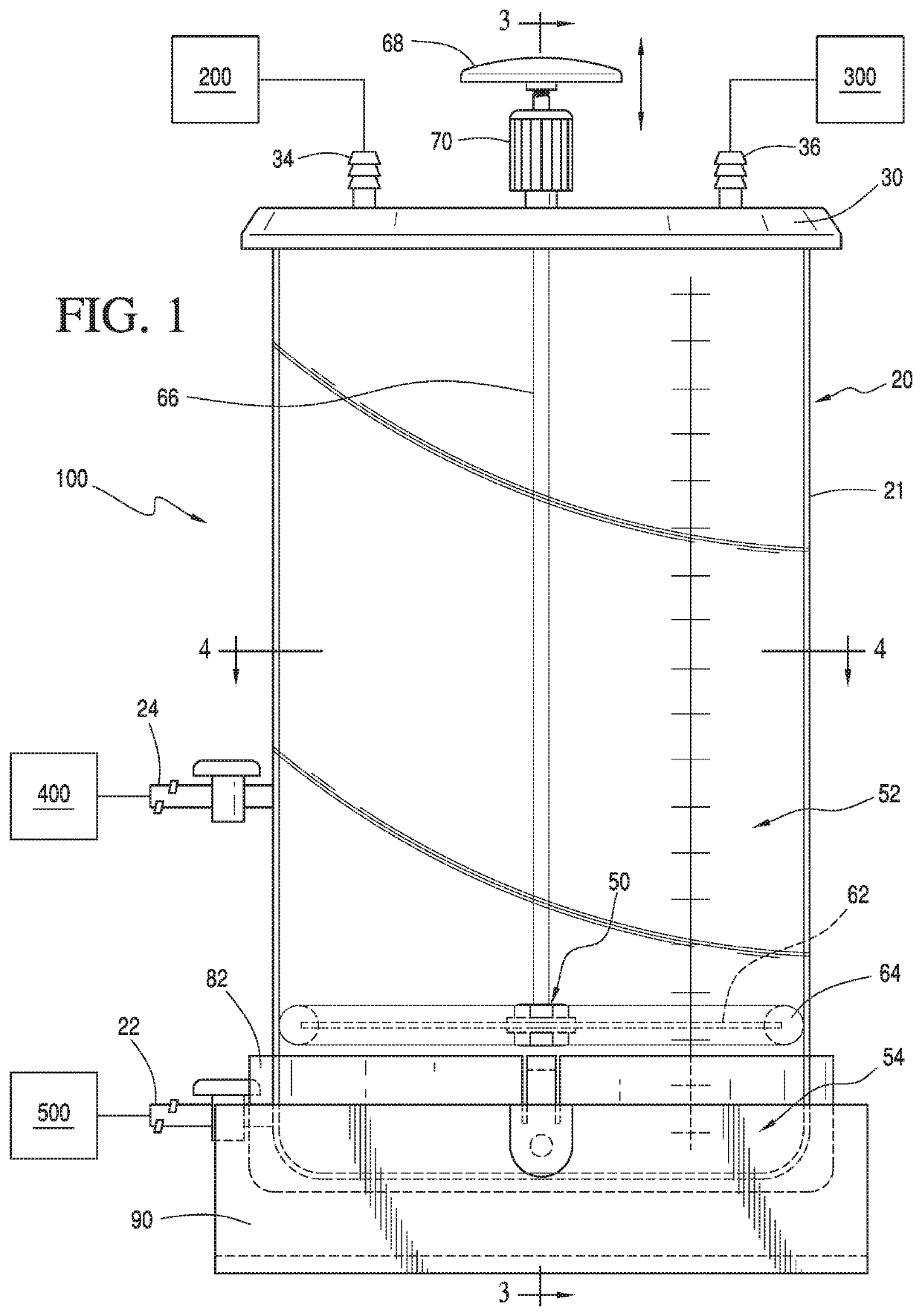
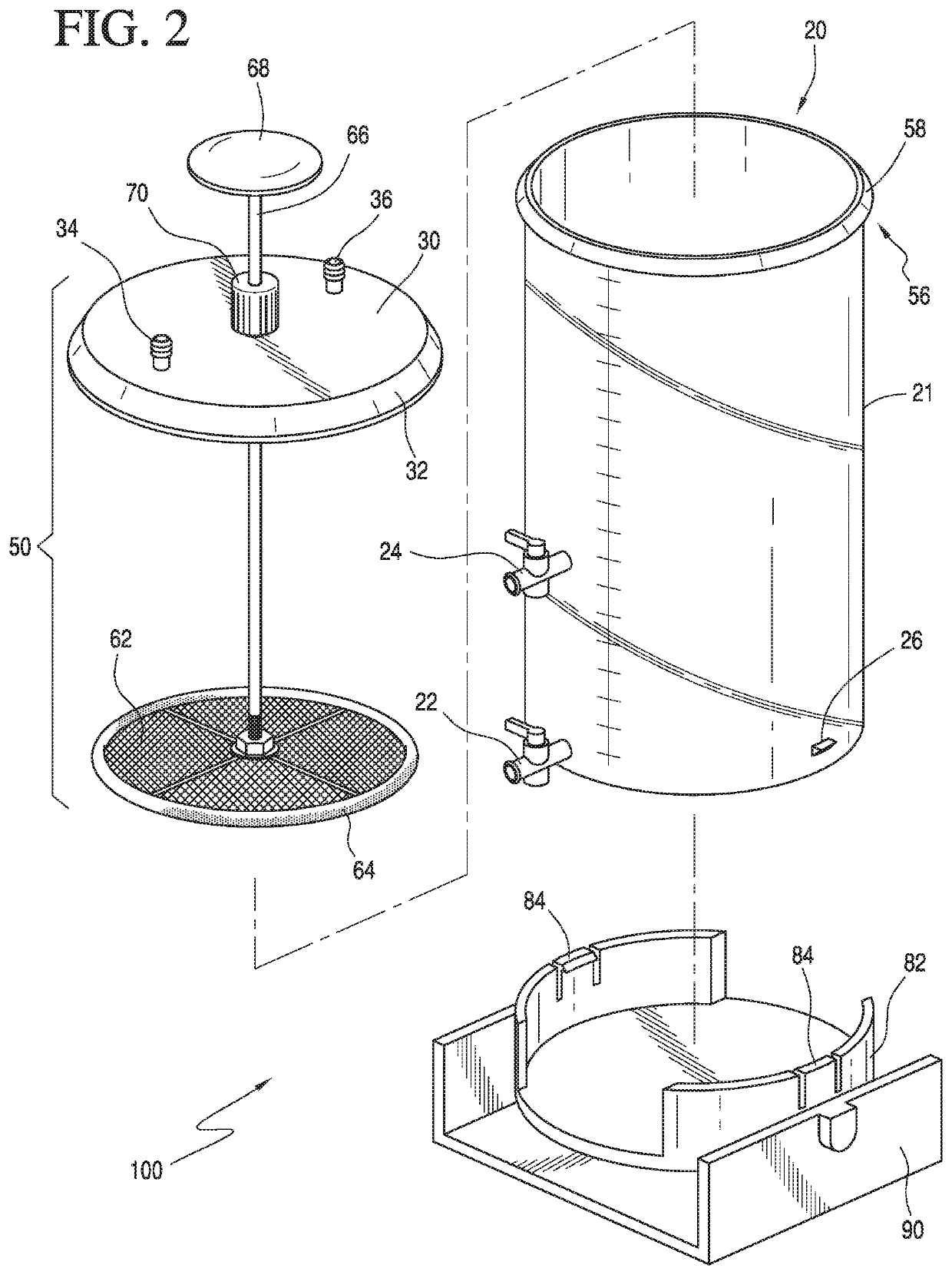
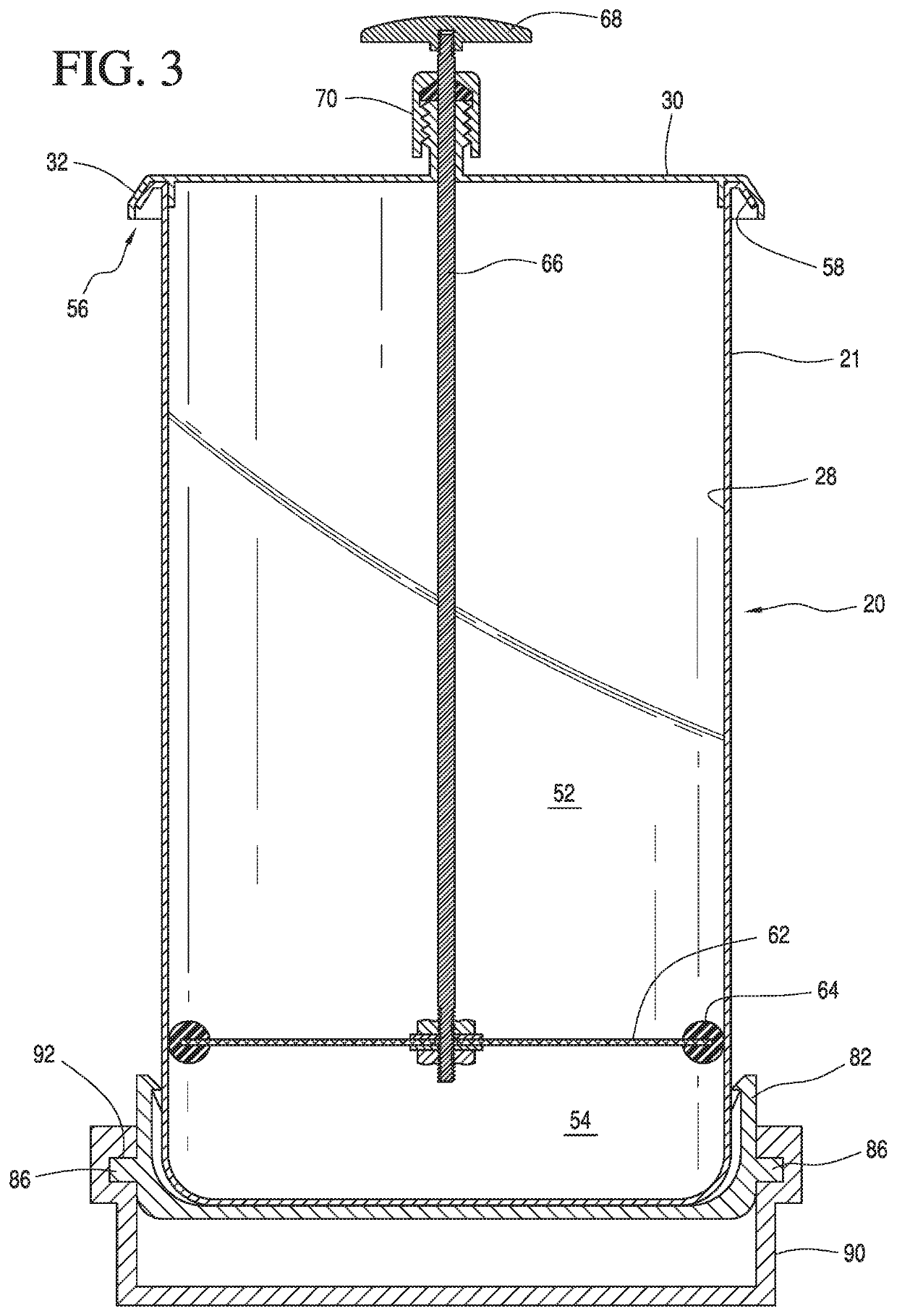
[0016]Referring to at least FIG. 1, a tissue separating device 100 in accordance with a preferred embodiment of the present teachings is shown. The tissue separating device 100 can include a canister device 20 including a canister body 21 and a lid 30. The canister device 20 can include a vacuum connector 34 and a tissue retrieval port 36 which can be arranged in the lid 30. The vacuum connector 34 can be operatively coupled to a vacuum source 200 via tubing. The tissue harvesting port 36 can be operatively coupled to a harvesting device 300 via a liposuction cannula. A sidewall of the canister body 21 can include a fluid evacuation port 22 and a tissue harvesting port 24. The tissue separating device 100 also includes an adjustable height filtration mesh assembly 50 that is operable to divide the interior of the canister device 20 into an upper vacuum chamber 52 and a lower vacuum chamber 54.

[0017]In use, a quantity of fatty liposuction aspirate can be directed into the canister de...


PUM


Abstract

A tissue separating device (100) is provided. The tissue separating device (100) includes a canister device (20) including a canister body (21) defining a volume. A tissue retrieval port (36) can be arranged on the canister device (20) and is capable of being arranged in fluid communication with a harvesting device (300) for directing a fatty liposuction aspirate into the volume of the canister device (20). An adjustable height filtration mesh assembly (50) can be arranged within the canister body (21) and can include a filtering mesh (62). A tissue harvesting port (24) can be arranged in the sidewall of the canister body (21) and can be capable of being arranged in communication with a collection device (400) to allow the tissue harvesting port (24) to atraumatically receive a filtered pure fat collected on the filtering mesh (62). The filtration mesh assembly (50) can be movably arranged within the canister body (21) such that the filtering mesh (62) is adjustable with respect to the tissue harvesting port (24).

Description

CROSS REFERENCE TO RELATED APPLICATIONS[0001]The present application is the national stage of International Application No. PCT / US2016 / 033896, filed internationally on May 24, 2016, which is a continuation of U.S. patent application Ser. No. 14 / 723,717 filed May 28, 2015, the disclosures of which are incorporated herein in their entirety by reference.FIELD OF THE INVENTION[0002]The present teachings relate to a tissue separating device for body fluids and tissue specimens. In particular, the present teachings relate to a separation device for use with a suction source to withdraw and separate body fluids and tissue specimens from a patient in an atraumatic manner.BACKGROUND OF THE INVENTION[0003]Autologous adipose tissue (or fatty tissue) transplantation is performed by many surgeons for various cosmetic and reconstructive procedures. Autologous fat transplantation involves retrieving adipose tissue using liposuction techniques from an area of abundance and then re-injecting the har...

Claims


Application Information

Patent Timeline
Patent Type & Authority Patents(United States)
IPC IPC(8): A61M1/00A61M5/178C12M1/33A61M27/00A61M5/315A61M5/00C12M1/00
CPCA61M1/0094A61M1/0005A61M1/0068A61M2202/0014A61M2202/0021C12M47/02A61M2205/7545A61M2202/09A61M2202/08C12M45/02A61M1/63A61M1/88A61M1/892A61M1/81
Inventor VENTURI, MARK LOUIS
Owner STRYKER CORP
Why Eureka
Try Eureka