
Patient examination system

a technology for examination systems and patients, applied in the direction of wheelchairs/patient conveyances, transportation and packaging, chairs, etc., can solve the problems of challenging compliance with certain requirements in regard to clinical furnitur

Active Publication Date: 2020-12-29
KRUG INC
View PDF25 Cites 3 Cited by
  • Summary
  • Abstract
  • Description
  • Claims
  • Application Information

AI Technical Summary

Benefits of technology

The invention is a patient examination system that can be raised and lowered to different positions for patient examination. The system includes a frame assembly and motion-controlling assemblies for moving the frame assembly relative to the floor. The frame assembly supports a seat subassembly with a seat cushion, a back subassembly with a back cushion, a footrest subassembly with a footrest cushion, and a cover element covering the seat and footrest cushions. The frame assembly can support the seat subassembly in a lowered position, a raised position, and intermediate positions. The back subassembly can support the back cushion in a non-horizontal position and a horizontal position. The footrest subassembly can support the footrest cushion in a retracted position and an extended position. The technical effect of the invention is to provide a patient examination system that can easily move to different positions for patient examination and provide comfortable support for the patient during the examination.

Problems solved by technology

The need to have two separate items of furniture has a number of disadvantages, e.g., a room in which the patient is examined is usually required to be sufficiently large to accommodate the two furniture items, as well as other equipment.
For example, in the United States, the Americans with Disabilities Act (“ADA”) imposes a number of requirements, and in the prior art, compliance with certain of the requirements in regard to clinical furniture has been found to be challenging.

Method used


Image

  • Patient examination system
  • Patient examination system
  • Patient examination system

Examples


Embodiment Construction

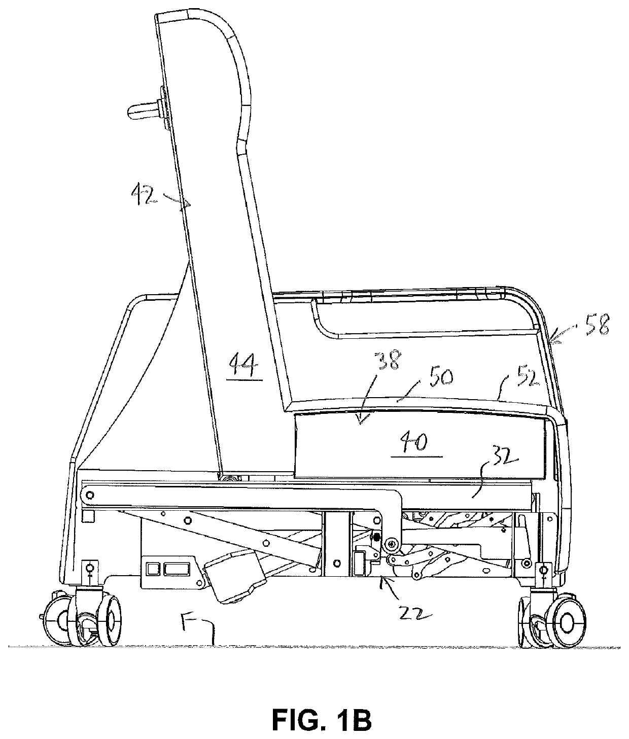
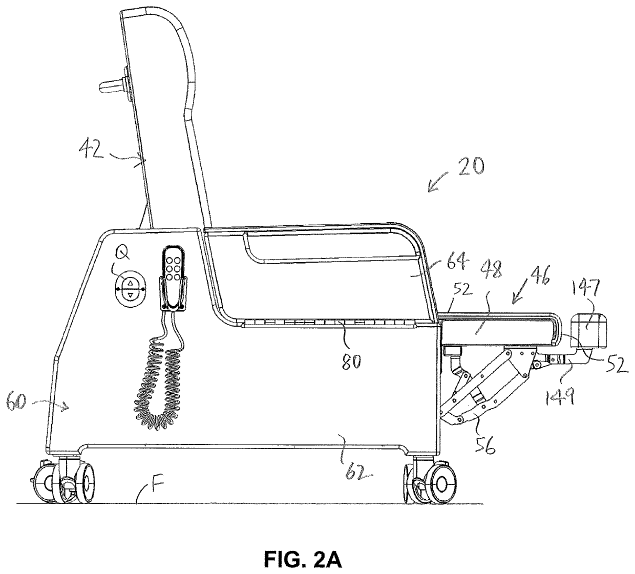
[0044]In the attached drawings, like reference numerals designate corresponding elements throughout. Reference is first made to FIGS. 1A-9D to describe an embodiment of a patient examination system of the invention indicated generally by the numeral 20. As will be described, the patient examination system for locating a patient (not shown) above a floor “F” supporting the patient examination system 20. In one embodiment, the patient examination system 20 preferably includes a frame assembly 22 (FIGS. 1B, 3B, 3C, 5B, 5C) having one or more lower elements 24 (FIGS. 3B, 5B) at least partially defining a lower side 26 of the frame assembly 22 that is located proximal to the floor “F”. Preferably, the patient examination system 20 also includes one or more motion-controlling assemblies 28 (FIG. 5B) connected to the frame assembly 22 for moving one or more selected movable portions 30 of the frame assembly 22 relative to the floor “F”. It is also preferred that the selected movable portio...


PUM


Abstract

A patient examination system for locating a patient above a floor. The patient examination system includes a frame assembly, one or more motion-controlling assemblies connected to the frame assembly for moving one or more selected movable portions of the frame assembly, and a patient support assembly that is supported by the frame assembly. The patient support assembly includes a seat subassembly, a back subassembly, a footrest subassembly, and a cover element covering a seat cushion and a footrest cushion in the footrest subassembly. The cover element has an exposed surface formed for engagement with the patient. The seat subassembly supports the seat cushion and is secured to the upper element of the frame assembly. The frame assembly is configured to support the seat subassembly relative to the floor in a lowered position thereof, in a raised position thereof, in intermediate seat positions therebetween, and in Trendelenburg positions.

Description

CROSS-REFERENCE TO RELATED APPLICATION[0001]This application claims the benefit of U.S. Provisional Patent Application No. 62 / 635,599, filed on Feb. 27, 2018, the entirety of which is hereby incorporated by reference.FIELD OF THE INVENTION[0002]The present invention is a patient examination system.BACKGROUND OF THE INVENTION[0003]As is well known in the art, two separate items of clinical furniture are needed in order to accommodate the variety of positions which may be requested of a patient. In the prior art, an examination table is used to support the patient in prone, supine, or side-lying positions. An examination chair typically is used to support the patient in a seated or semi-supine position. The need to have two separate items of furniture has a number of disadvantages, e.g., a room in which the patient is examined is usually required to be sufficiently large to accommodate the two furniture items, as well as other equipment.[0004]Legislation in various jurisdictions has i...

Claims


Application Information

Patent Timeline
IPC IPC(8): A47G5/02A47C1/03A47C7/54A61G15/02A61G13/00A61G13/12A61G5/02A47C1/034A61G13/06A61G13/08
CPCA61G15/02A47C1/0308A47C7/543A61G5/025A61G13/0018A61G13/125A61G13/129A47C1/0342A61G13/06A61G13/08A61G2200/322A61G2200/325A61G2200/327A61G2200/34A61G7/16A61G15/12
Inventor RUBY, LEONARDFERNANDES, CESARPARK, KYUNGHUN
Owner KRUG INC
Learn More