
Device and method for calculating required navigation performance prediction

a technology of required navigation and prediction method, applied in the field of flight management systems, can solve the problems of inertial drift, limited knowledge of required navigation performance, and error considered negligible, so as to improve the control of the trajectory of the aeroplane and the expected and available performance

Active Publication Date: 2020-12-15
THALES SA
View PDF38 Cites 1 Cited by
  • Summary
  • Abstract
  • Description
  • Claims
  • Application Information

AI Technical Summary

Benefits of technology

[0028]Advantageously, the device of the invention provides in a simple manner a corridor trajectory piece of information, allowing the operator of the aircraft better control of the aeroplane's trajectory and of the expected and available performance, by giving him easy access to the corridor in which the performance is guaranteed and to the limits not to be exceeded. Through the immediate viewing of the navigation latitude in a corridor, the avoidance of an obstacle becomes an operation which is easy for the pilot to undertake, without requesting prior authorization or with a very early request since the operator or the pilot by virtue of the knowledge of the estimated performance, complies with the safety which is displayed to him in an obvious manner by the corridor trajectory.

Problems solved by technology

As regards inertial means, they suffer from the problem of inertial drift inherent in these systems.
This error characterizes the error in the calculation of the aeroplane position on the basis of radio position, inertial, or satellite sensors.
This error is considered to be negligible, since it is associated with a very improbable error of coding of the navigation database.
Thus, at present the knowledge of the required navigation performance remains limited to the current flight segment, or indeed to near the end of the next segment, whilst the value of the required navigation performance can vary along the whole flight plan.
Thus, knowledge of the estimated navigation performance remains limited to the current position of the aircraft and does not allow the pilot to anticipate with regard to non-compliance with the required performance.
However, with the wire display, the operator does not have any information about the navigation latitude in the corridor which is defined by the required navigation performance, and if an obstacle lies in the corridor, the pilot will see it only at the last moment and the operation will require an emergency authorization request to the ground operator.
Moreover, the known navigation systems do not afford the operator the “freedom” to navigate in a defined corridor while complying with the RNP procedure.

Method used


Image

  • Device and method for calculating required navigation performance prediction
  • Device and method for calculating required navigation performance prediction
  • Device and method for calculating required navigation performance prediction

Examples


Embodiment Construction

[0087]FIG. 5 represents an exemplary display according to one embodiment of the invention, of the estimated navigation performance (EPU) prediction for a wire trajectory associated with a list of segments. This display allows the operator to monitor the aircraft navigation performance. A list of segments such as defined in the description is a continuous sequence of segments (S1, S2, . . . , Si, . . . , Sn), the segments being straight or curved, each segment having a start point (PDSi) and a final point (PFSi) respectively defined by their latitude, longitude and altitude. Moreover, with any segment of a list is associated a transit time when passing over the final point of the segment, and one speaks of a dated list of segments. In the example of FIG. 5, five segments (S1 to S5) of a list of segments Sn are represented. The segment S1 which has start point PDS1 and final point PFS1 contains the representation of the aircraft in its current position, the segment S2 which has start ...


PUM


Abstract

A method is provided for calculating the prediction of required navigation performance for a trajectory associated with a list of segments of a flight plan. A method is also provided for displaying the navigation performance as a corridor trajectory and adapted to guarantee compliance with the navigation performance requirements while offering immediate viewing of the navigation latitude in a corridor.

Description

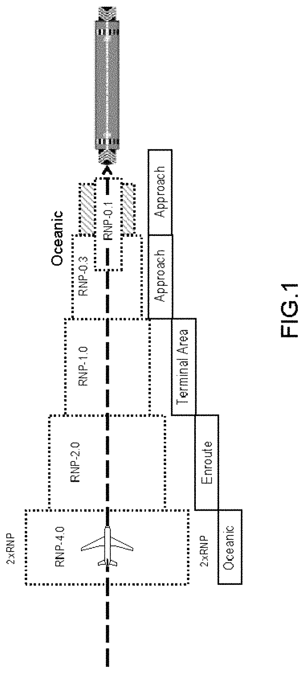
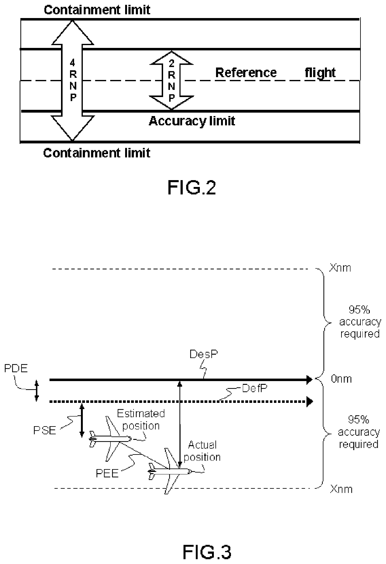
CROSS-REFERENCE TO RELATED APPLICATIONS[0001]This application claims priority to foreign French patent application No. FR 1601060, filed on Jul. 7, 2016, the disclosure of which is incorporated by reference in its entirety.FIELD OF THE INVENTION[0002]The invention relates to the field of flight management systems, and more particularly that of aiding the piloting of aircraft through the early calculation of navigation performance.BACKGROUND[0003]So-called Performance-Based Navigation (PBN) is a flight scheme which was defined by the ICAO international civil aviation organization in 1998 in order to optimize the use of airspace faced with the continual growth in air traffic. The PBN scheme makes it possible to define conditions to be complied with in terms of integrity, availability, functionality, accuracy and continuity. These conditions are manifested by requirements in terms of Required Navigation Performance (RNP) and in terms of estimated navigation performance EPE (Estimated P...

Claims


Application Information

Patent Timeline
Patent Type & Authority Patents(United States)
IPC IPC(8): G05D1/10G08G5/00G01C23/00G05D1/02
CPCG08G5/0021G08G5/0034G08G5/0052G08G5/0047G08G5/0039G05D1/101G01C23/005G05D1/02
Inventor ROGER, MICHELPIERRE, CHRISTOPHEGOUTELARD, HERVÉ
Owner THALES SA
Learn More