
Self-powered miniature mobile sensing device

a mobile sensing device and self-powered technology, applied in piezoelectric/electrostrictive/magnetostrictive devices, electrical apparatus, surveys, etc., can solve the problems of wireline logging, wireline logging tool stuck, and add to the cost of drilling a well, so as to achieve less power to operate and not easily replicable

Active Publication Date: 2020-11-24
SAUDI ARABIAN OIL CO
View PDF69 Cites 0 Cited by
  • Summary
  • Abstract
  • Description
  • Claims
  • Application Information

AI Technical Summary

Benefits of technology

MMSDs provide efficient, cost-effective, and flexible monitoring and control capabilities, enabling high-resolution data collection and transmission, reducing the need for batteries and minimizing power consumption, while withstanding high temperatures and harsh environments.

Problems solved by technology

Wireline logging is expensive due to the time spent on performing a wireline logging operation as well as the expensive sensors and packaging.
Moreover, there is always the risk of a wireline logging tool getting stuck in the hole, which could significantly add to the cost of drilling a well.
MWD / LWD are very expensive, bulky and lengthy tools and mud pulse rate is generally slow (maximum of up to 20 bits / second in the field).
Near-bit tools have gamma ray and inclination sensors 3-10 feet away from the bit but the number of sensors that can be placed near a bit is limited and the sensors are exposed extremely harsh environment, which may affect its performance and lifespan compared to sensor modules located further above the bit.
If the drilling assembly contains a mud motor above the near-bit tools, additional data transmission means (data hoop from sensors to mud pulser) are needed to ensure real-time data transmission to surface, which adds considerable technical complexities and therefore prone to problems while operating the tools.
Batteries can also be used to provide power to the MMSDs but batteries are not easily replicable and generally cease to function at high temperatures (>125° C.).
Batteries can also be used to provide power to the MMSDs but batteries are not easily replicable and cease to function at high temperatures.
Packaging and encapsulation is mainly done to protect the MMSD components from mud and other fluids in the formation, which may degrade its performance.

Method used


Image

  • Self-powered miniature mobile sensing device
  • Self-powered miniature mobile sensing device
  • Self-powered miniature mobile sensing device

Examples


Embodiment Construction

[0024]The methods and systems of the present disclosure will now be described more fully hereinafter with reference to the accompanying drawings in which embodiments are shown. The methods and systems of the present disclosure may be in many different forms and should not be construed as limited to the illustrated embodiments set forth herein; rather, these embodiments are provided so that this disclosure will be thorough and complete, and will fully convey its scope to those skilled in the art. The term “high temperature” as referred to herein refers to temperatures above 125° C. unless otherwise noted.

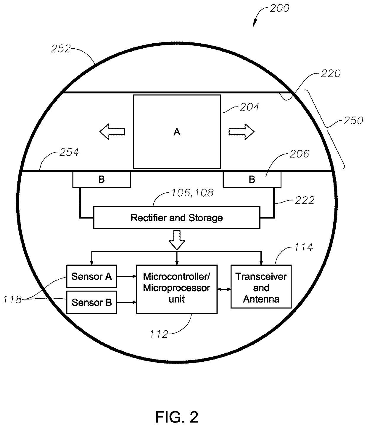
[0025]Turning now to the figures, FIG. 1 illustrates a smart miniature mobile sensing device (MMSD) 100 with a power generator 250, integrated sensors 118, microcontroller / microprocessor 112 and a communication module 114 that can be injected into wells to evaluate, characterize downhole environments as well as control downhole equipment. These MMSDs have the ability to perform the s...


PUM


Abstract

A device for wirelessly monitoring well conditions includes a power including a first material attached to edges of at least one lever suspended about a central fulcrum, wherein the edges of the at least one lever are free to move about the central fulcrum, a frictionless movable object disposed inside the body of the at least one lever, wherein the frictionless movable object is free to move within the body of the at least one lever, and a second material that is fixed in position relative to the first material, wherein the first material and second material are of opposite polarities.

Description

BACKGROUND1. Field[0001]Embodiments of the present disclosure relate to systems and methods for wirelessly monitoring well conditions using high temperature, self-powered, miniature mobile sensing devices including a power generator that generates power based on friction, generated by fluid or mud flow, between two materials of opposite polarity.2. Description of Related Art[0002]Logging tools, such as wireline logging tools, MWD (measurement while drilling) and LWD (logging while drilling) are used to obtain information about the geological formations both inside and surrounding limited wellbore regions. The information obtained by these downhole measurement tools can be used to make various interpretations about the formations and conditions inside a well, which can then be used to make and revise drilling programs. Wireline and MWD / LWD tools have the ability to measure, either directly or indirectly, a wide range of measurements such as wellbore trajectory, and formation characte...

Claims


Application Information

Patent Timeline
Patent Type & Authority Patents(United States)
IPC IPC(8): E21B41/00E21B47/13H01L41/113H02N2/18H02N1/04E21B47/00E21B49/00H10N30/30
CPCH02N1/04E21B41/0085E21B47/13E21B47/00E21B49/00E21B47/017E21B47/26E21B47/138
Inventor GOONERATNE, CHINTHAKA PASANLI, BODONG
Owner SAUDI ARABIAN OIL CO
Learn More