Air cooling system for sealed attic building structures

a cooling system and sealed attic technology, applied in ventilation systems, lighting and heating apparatus, heating types, etc., can solve the problems of energy loss and moisture build-up in the attic, the difficulty of building a vented roof assembly with an airtight interior barrier at the ceiling plane, and the high cost of the system to opera

Active Publication Date: 2020-11-10
QC MFG
View PDF71 Cites 17 Cited by
  • Summary
  • Abstract
  • Description
  • Claims
  • Application Information

AI Technical Summary

Benefits of technology

The patent describes a temperature regulating system for buildings with sealed attics. The system includes a fan, air intake, vent, damper, and flow path for circulating outside air through the building structure. The system can modify the flow path based on the temperature conditions of the living space, attic, and outside environment. The system has thermally-insulated dampers to prevent heat transfer between the attic and living space, and a duct to prevent air from entering the vent. The system also has an air intake and an opening to control air flow through the intake. The method involves opening a damper to create a negative pressure in the space, drawing in air from the outside, and powering a whole house fan to cool the building. The vent assembly includes a whole house fan, motor housing, and a flange that creates a watertight interface. The damper is movable between an open and closed configuration to control air flow. The technical effects of the patent are improved temperature regulation for buildings with sealed attics and a reduction in heat transfer between the attic and living space.

Problems solved by technology

But complex roof designs make it difficult to construct a vented roof assembly with an airtight interior barrier at the ceiling plane.
Such ductwork is often leaky or less well insulated, resulting in energy losses and moisture build up in the attic as air flows between the conditioned living space and the vented attic.
However, most cooling systems designed for a building structure having an unvented attic rely on air-conditioning systems that use a refrigeration cycle to cool the air.
Such systems can be expensive to operate and limit the flow of fresh air into the building.

Method used


Image

  • Air cooling system for sealed attic building structures
  • Air cooling system for sealed attic building structures
  • Air cooling system for sealed attic building structures

Examples


Embodiment Construction

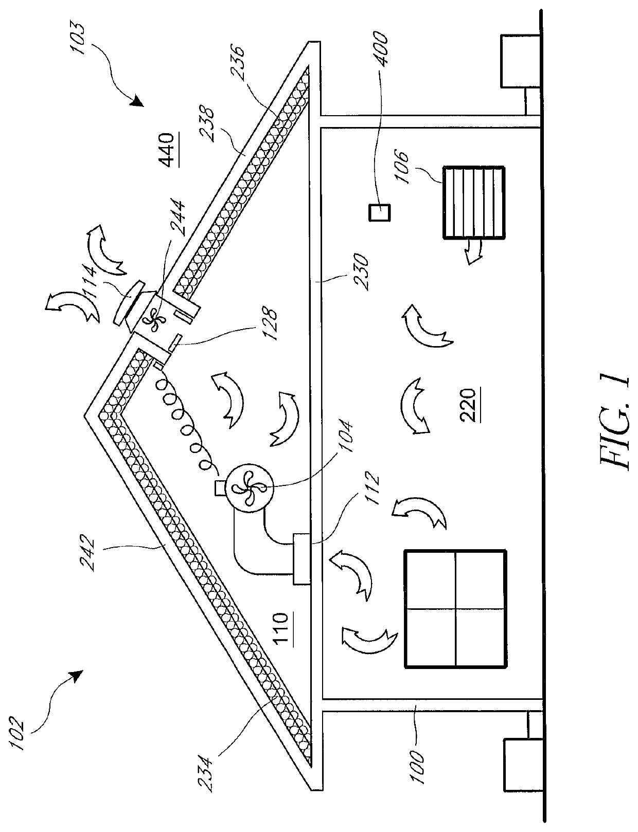
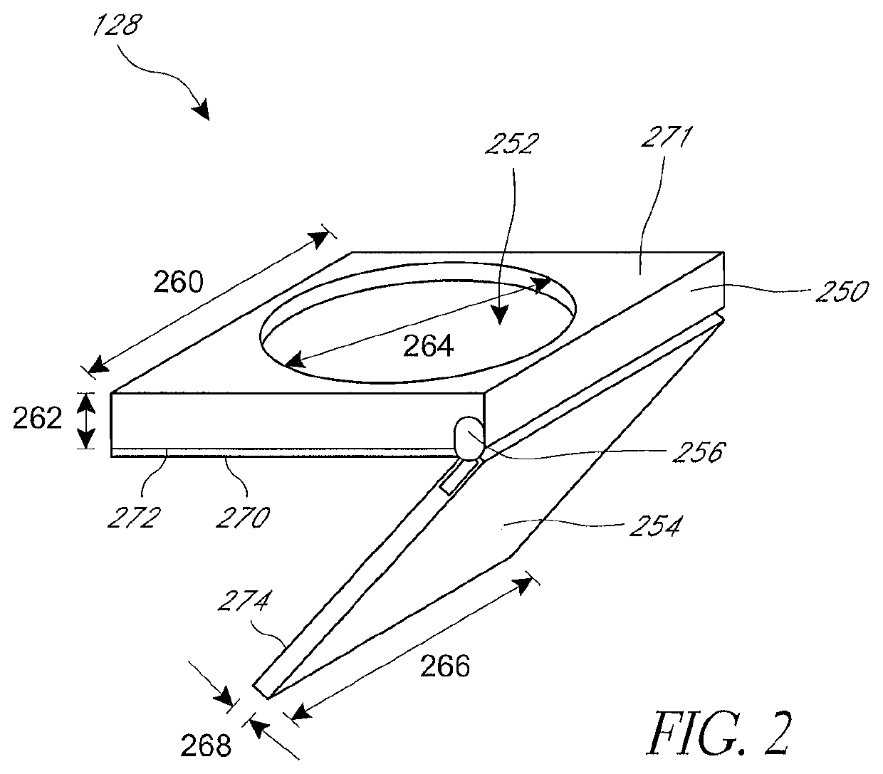
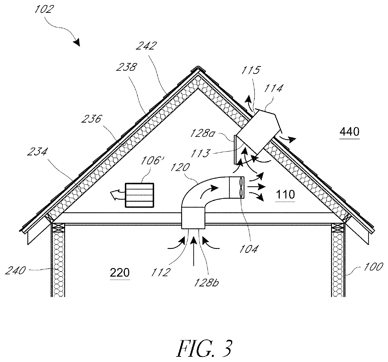
[0030]Embodiments of systems, components and methods of assembly and manufacture will now be described with reference to the accompanying figures, wherein like numerals refer to like or similar elements throughout. Although several embodiments, examples and illustrations are disclosed below, it will be understood by those of ordinary skill in the art that the inventions described herein extends beyond the specifically disclosed embodiments, examples and illustrations, and can include other uses of the inventions and obvious modifications and equivalents thereof. The terminology used in the description presented herein is not intended to be interpreted in any limited or restrictive manner simply because it is being used in conjunction with a detailed description of certain specific embodiments of the inventions. In addition, embodiments of the inventions can comprise several novel features and no single feature is solely responsible for its desirable attributes or is essential to pra...


PUM


Abstract

A fresh-air cooling system for a building structure having an unvented attic is provided. The system provides airflow pathways that allow outside air to be drawn through, and discharged from, a building having an unvented attic. Dampers with a low thermal conductivity regulate airflow through the building structure. The system allows a whole house fan to cool a building having an unvented attic. The system seals or otherwise alters airflow pathways through the building structure in order to reduce heat transfer between the building and the outside environment when the cooling system is not in use.

Description

INCORPORATION BY REFERENCE TO ANY PRIORITY APPLICATIONS[0001]Any and all applications for which a foreign or domestic priority claim is identified in the Application Data Sheet as filed with the present application are hereby incorporated by reference under 37 CFR 1.57.BACKGROUNDField[0002]The disclosure relates generally to cooling systems for building structures, such as those having sealed envelope attics.Description of the Related Art[0003]Traditionally, homes have been built with a ventilated attic to help keep the house cooler in the summer and discourage moisture buildup in the attic year-round. In a vented attic, warm attic air rises to the peak of the roof and escapes the attic through a vent near the peak of the roof. The warm air escaping the attic creates a suction force that draws outside air into the attic through other vents (e.g., soffit vents). In this way, attic air is circulated in a vented attic.[0004]In cold climates, attic ventilation helps maintain a cold roof...

Claims


Application Information

Patent Timeline
IPC IPC(8): F24F7/02F24F7/007F24F11/00
CPCF24F7/025F24F7/007F24F11/0001F24F2221/14F24F2221/16F24F2110/10
Inventor STEVENSON, DANA CHARLES
Owner QC MFG
Why Eureka
Try Eureka