
Local contraction of flexible bodies using balloon expansion for extension-contraction catheter articulation and other uses

a flexible body and local contraction technology, applied in the field of elongated flexible body articulation, can solve the problems of imposing significant trauma to collateral tissues, serious pain to patients, serious damage to patients' health, etc., and achieves the effects of modulating the stiffness reducing the length of the elongated body, and reducing the pain of patients

Active Publication Date: 2020-10-20
PROJECT MORAY INC
View PDF139 Cites 8 Cited by
  • Summary
  • Abstract
  • Description
  • Claims
  • Application Information

AI Technical Summary

Benefits of technology

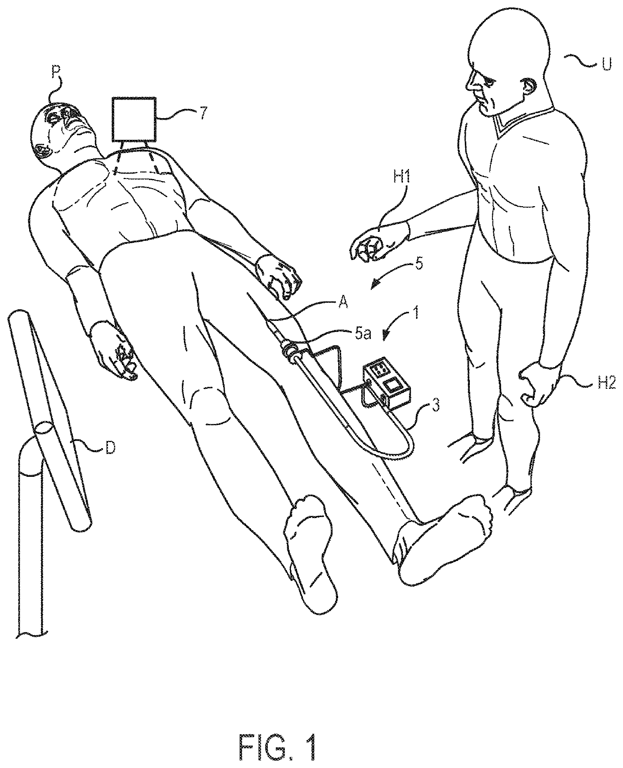
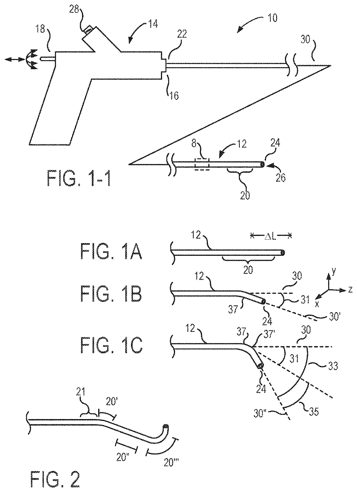
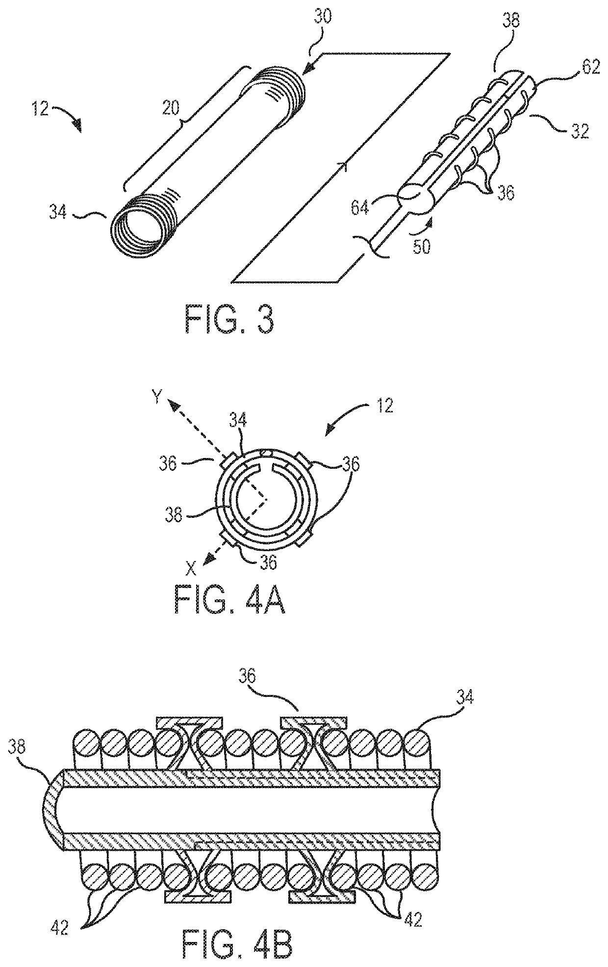
The present invention provides articulation devices and systems for elongate flexible structures, such as medical catheters and guidewires. The invention includes a fluid-driven balloon array that can be used to selectively bend, alter the bend characteristics, or change the lengths of elongate flexible structures. The skeleton structures of the invention have pairs of surface regions that move relative to each other, and a balloon between them can axially contract or shorten the skeleton, for example, bending it towards a different balloon. The invention allows for controlled inflation and deflation of balloons to modulate the stiffness of the elongate body without changing its position.

Problems solved by technology

Unfortunately, gaining access to and aligning tools with the appropriate internal tissues for evaluation or treatment can represent a significant challenge to the physician, can cause serious pain to the patient, and may (at least in the near term) be seriously detrimental to the patient's health.
Although open surgical techniques have been highly successful, they can impose significant trauma to collateral tissues, with much of that trauma being associated with gaining access to the tissues to be treated.
In fact, some endoluminal techniques that are relatively simple in concept can be very challenging (or even impossible) in practice (depending on the anatomy of a particular patient and the skill of a particular physician).
As the flexible elongate body advances around first one curve and then another, and through a series of branch intersections, the catheter / tissue frictional forces, resilient energy storage (by the tissue and the elongate body), and other movement interactions may become more complex and unpredictable, and control over the rotational and axial position of the distal end of a catheter can become more challenging and less precise.
Hence, accurately aligning these elongate flexible devices with the desired luminal pathway and target tissues can be a significant challenge.
Unfortunately, as articulation systems for catheters get more complex, it can be more and more challenging to maintain accurate control over these flexible bodies.
Hysteresis and friction of a pull-wire system may vary significantly with different overall configurations of the bends, so that the articulation system response may be difficult to predict and control.
These attempts to provide automated catheter control have met with challenges, which may be in-part because of the difficulties in providing accurate control at the distal end of a flexible elongate body using pull-wires extending along bending body lumens.
While the potential improvements to control surgical accuracy make all of these efforts alluring, the capital equipment costs and overall burden to the healthcare system of these large, specialized systems is a concern, and precise robotic control of some or all of these system can still be a challenge.

Method used


Image

  • Local contraction of flexible bodies using balloon expansion for extension-contraction catheter articulation and other uses
  • Local contraction of flexible bodies using balloon expansion for extension-contraction catheter articulation and other uses
  • Local contraction of flexible bodies using balloon expansion for extension-contraction catheter articulation and other uses

Examples


Embodiment Construction

[0056]The catheter bodies (and many of the other elongate flexible bodies that benefit from the inventions described herein) will often be described herein as having or defining an axis, such that the axis extends along the elongate length of the body. As the bodies are flexible, the local orientation of this axis may vary along the length of the body, and while the axis will often be a central axis defined at or near a center of a cross-section of the body, eccentric axes near an outer surface of the body might also be used. It should be understood, for example, that an elongate structure that extends “along an axis” may have length that extends in an orientation with a significant axial component, but the length of that structure need not be precisely parallel to the axis. Similarly, an elongate structure that extends “primarily along the axis” and the like will generally have a length that extends along an orientation that has a greater axial component than components in other or...


PUM


Abstract

Articulation devices, systems, and methods for articulating elongate flexible structures can locally contract a flexible elongate frame or skeleton of an elongate flexible body such as a catheter. Balloons along one side of an axial segment of the elongate flexible body can be inflated so as to help define a resting shape of the elongate body. The skeleton may have pairs of corresponding axially oriented surface regions coupled to each other by a loop of a deformable helical coil structure. Balloons may be between the regions, and the pairs may be separated by an offset that increases when the axis of the skeleton is axially compressed. Inflation of the balloons can axially contract or shorten the skeleton adjacent the balloons so that the elongate body bends toward the balloons. Different sets of balloons may apply opposing local axial elongation and contraction forces so that selective inflation and deflation of subsets of the balloons can controllably bend and / or change an overall axial length of the elongate body throughout a workspace. Varying the inflation pressures of the opposed balloons can controllably and locally modulate the stiffness of the elongate body.

Description

CROSS REFERENCE TO RELATED APPLICATIONS[0001]The present application claims the benefit of priority from co-assigned U.S. Provisional Patent App. Nos. 62 / 296,409, filed on Feb. 17, 2016, entitled “LOCAL CONTRACTION OF FLEXIBLE BODIES USING BALLOON EXPANSION FOR EXTENSION-CONTRACTION CATHETER ARTICULATION AND OTHER USES”; and 62 / 401,005 filed on Sep. 28, 2016, entitled “BASE STATION CHARGER AND SERVER FOR HANDHELD ROBOTIC CATHETER SYSTEMS AND OTHER USES, AND IMPROVED ARTICULATED DEVICES AND SYSTEMS”, the full disclosures of which are incorporated herein for all purposes.[0002]The subject matter of the present application is related to that of co-assigned U.S. patent application Ser. No. 15 / 081,026 filed on Mar. 25, 2016, entitled “Articulation Systems, Devices, and Methods for Catheters and Other Uses” (US Patent Publication No. US20160279388; and to that of co-assigned U.S. patent application Ser. No. 15 / 369,606, filed on Dec. 5, 2016, entitled “Input and Articulation System for Cat...

Claims


Application Information

Patent Timeline
Patent Type & Authority Patents(United States)
IPC IPC(8): A61M25/01A61B90/00A61M25/00A61F7/00A61F7/12A61B18/00A61B18/14A61B34/30A61B17/00A61M25/10
CPCA61B90/361A61M25/005A61M25/0075A61M25/0136A61B90/37A61M25/0155A61B2090/378A61B2034/301A61B18/1492A61M2205/3337A61B2017/00318A61B18/00A61B2090/371A61B2017/00557A61M2025/0161A61F7/00A61M25/1018A61F7/12A61B2017/00314
Inventor LABY, KEITH PHILLIPBOURANG, HENRYBARRISH, MARK D.
Owner PROJECT MORAY INC
Learn More