
DC switching apparatus with auxiliary contact device using microswitch

a technology of auxiliary contact and switching apparatus, which is applied in the direction of magnetic/electric field switches, magnetic micromechanical switches, electromagnetic relay details, etc., can solve the problems of degrading the reliability difficult operation, and degrading the airtight sealing of the epoxy, so as to facilitate the utilization prevent the malfunction of the auxiliary contact, and increase the space distance

Active Publication Date: 2020-09-29
YMTECH
View PDF11 Cites 2 Cited by
  • Summary
  • Abstract
  • Description
  • Claims
  • Application Information

AI Technical Summary

Benefits of technology

The present invention provides an auxiliary contact for a sealed DC relay that can protect a microswitch from damage caused by opening and closing of the main contact. The auxiliary contact can transmit electrical signals accurately while monitoring the main contact's operation. The invention also includes a design that prevents the auxiliary contact from malfunctioning due to arc heat. Additionally, the invention provides a method and apparatus for soldering a microswitch onto a PCB, accurately soldering an externally connected terminal, and minimizing infiltration of carbon material generated during contact opening and closing. Furthermore, the invention prevents corrosive gas from entering the contact portion, making it an ideal solution for applications that require high reliability and durability.

Problems solved by technology

At this time, airtight sealing of epoxy is degraded due to soldering, insulation between a main contact and an auxiliary contact is destroyed due to soldering of a covered wire between the externally taken-out terminals of the auxiliary contact, an operation is difficult, the reliability of the auxiliary contact is degraded due to an arc voltage and arc heat, and burning occurs.

Method used


Image

  • DC switching apparatus with auxiliary contact device using microswitch
  • DC switching apparatus with auxiliary contact device using microswitch
  • DC switching apparatus with auxiliary contact device using microswitch

Examples


Embodiment Construction

[0038]The present invention will now be described more fully with reference to the accompanying drawings, in which exemplary embodiments of the invention are shown. The present invention may, however, be embodied in many different forms and should not be construed as being limited to the embodiments set forth herein.

[0039]The terminology used herein is for the purpose of describing particular embodiments only and is not intended to limit the present invention. As used herein, the singular forms “a”, “an” and “the” are intended to include the plural forms as well, unless the context clearly indicates otherwise.

[0040]It will be understood that the terms “comprises” and / or “comprising,” when used in this specification, specify the presence of stated components, steps, operations, and / or elements thereof, but do not preclude the presence or addition of one or more other components, steps, operations, and / or elements thereof.

[0041]While such terms as “first”, “second”, etc., may be used ...


PUM


Abstract

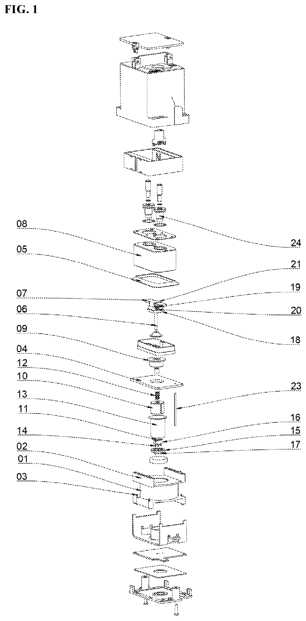
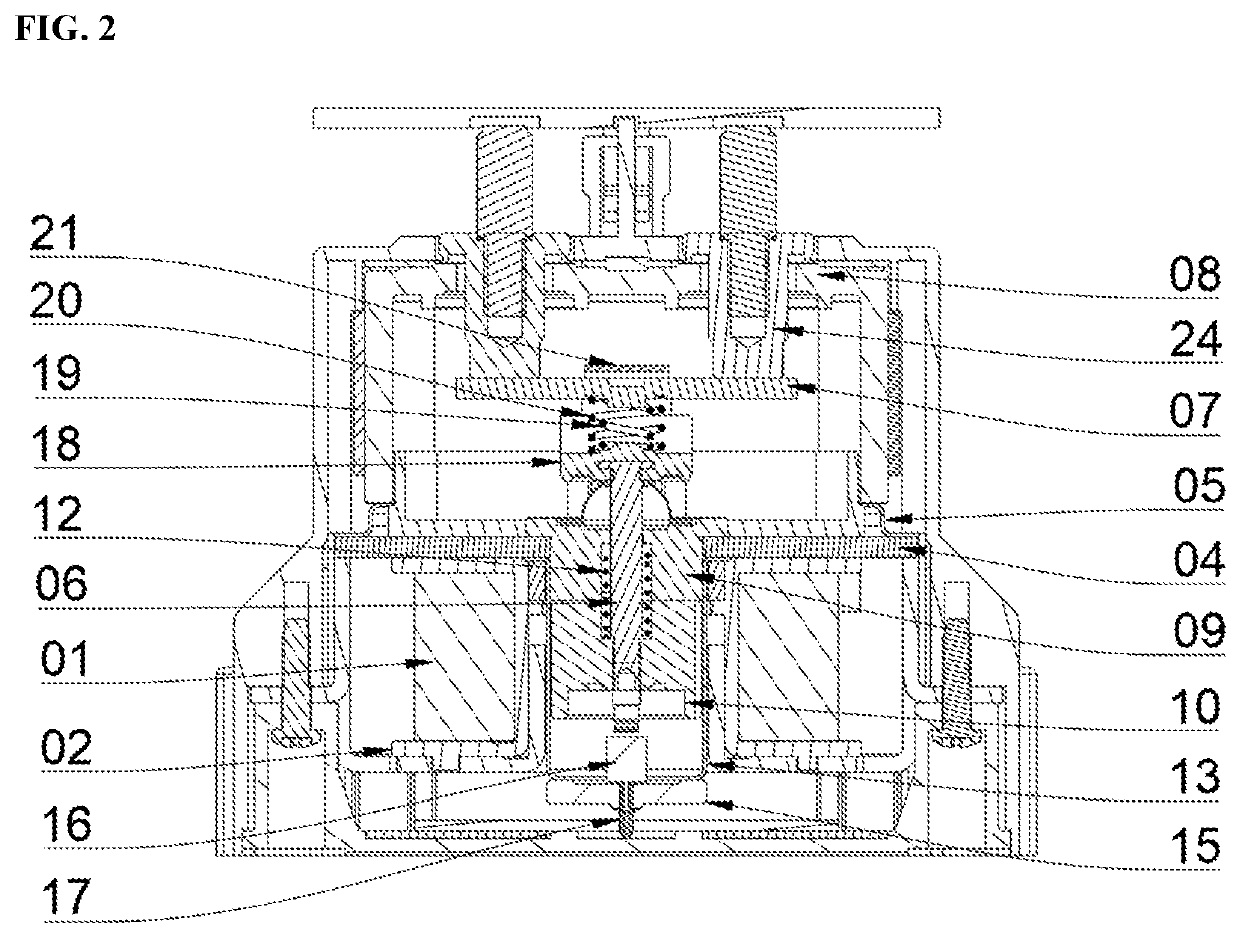
A direct current (DC) switching apparatus is provided. The DC switch apparatus includes an auxiliary contact device includes at least one pair of stationary contacts; one or more coils, a movable iron core that is driven by the one or more coils; a movable contact table operating in engagement with the movable iron core, and an auxiliary contact device arranged below the movable iron core. The auxiliary contact device includes a microswitch.

Description

CROSS-REFERENCE TO RELATED APPLICATION[0001]This application claims priority to Korean Patent Application No. 10-2019-0057455 filed on May 16, 2019, the entire contents of which are herein incorporated by reference.TECHNICAL FIELD[0002]The present invention relates to a direct current (DC) switching apparatus (relay) having an auxiliary contact device using a microswitch. More specifically, the present invention relates to a structure of an auxiliary contact device included in a DC high-voltage contact switching apparatus that is applicable to new renewable energy, electric vehicles, DC power control, battery power control, and the like.BACKGROUND ART OF THE INVENTION[0003]Direct current (DC) switching apparatuses may be used in new renewable energy (such as, solar energy generation), energy storage devices, and DC transportation systems such as electric bus rapid-charging devices. Recent energy storage devices and recent electric bus rapid-charging systems tend to increase a voltag...

Claims


Application Information

Patent Timeline
IPC IPC(8): H01H67/02H01H36/00
CPCH01H36/00H01H2036/0093H01H50/023H01H50/545H01H2050/025H01H9/0066
Inventor CHO, HYUN KILHONG, SU PYOLEE, SEUNG MIN
Owner YMTECH
Learn More