
Rainbow particle imaging velocimetry for dense 3D fluid velocity imaging

a 3d fluid velocity and imaging velocimetry technology, applied in the field of fluid capture, can solve the problems of difficult input data, difficult to achieve and difficult to achieve the reconstruction of all three components of the velocity field over the full 3d volume, etc., to achieve the effect of simplifying the identification of representative colors

Active Publication Date: 2020-09-22
KING ABDULLAH UNIV OF SCI & TECH
View PDF5 Cites 2 Cited by
  • Summary
  • Abstract
  • Description
  • Claims
  • Application Information

AI Technical Summary

Benefits of technology

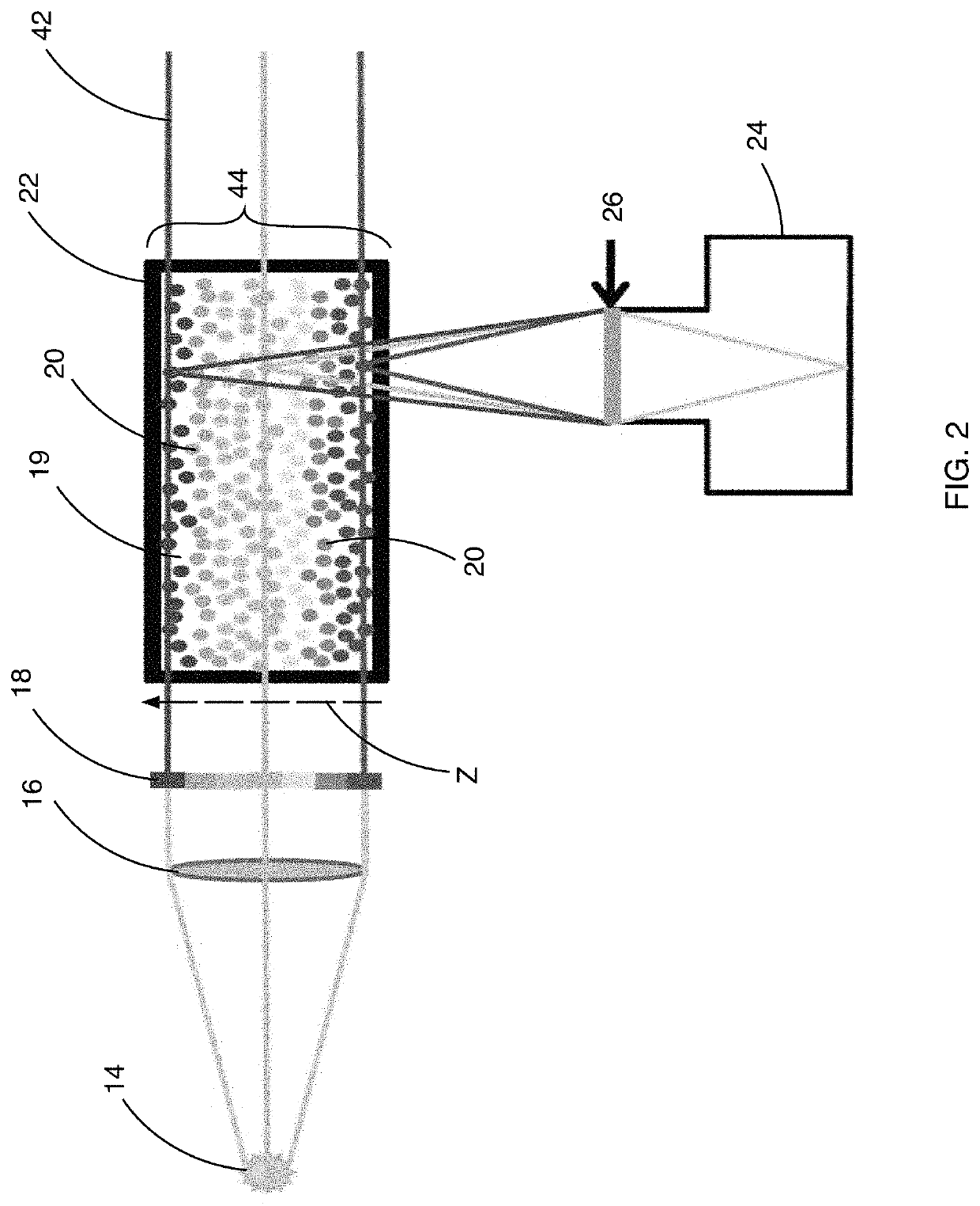
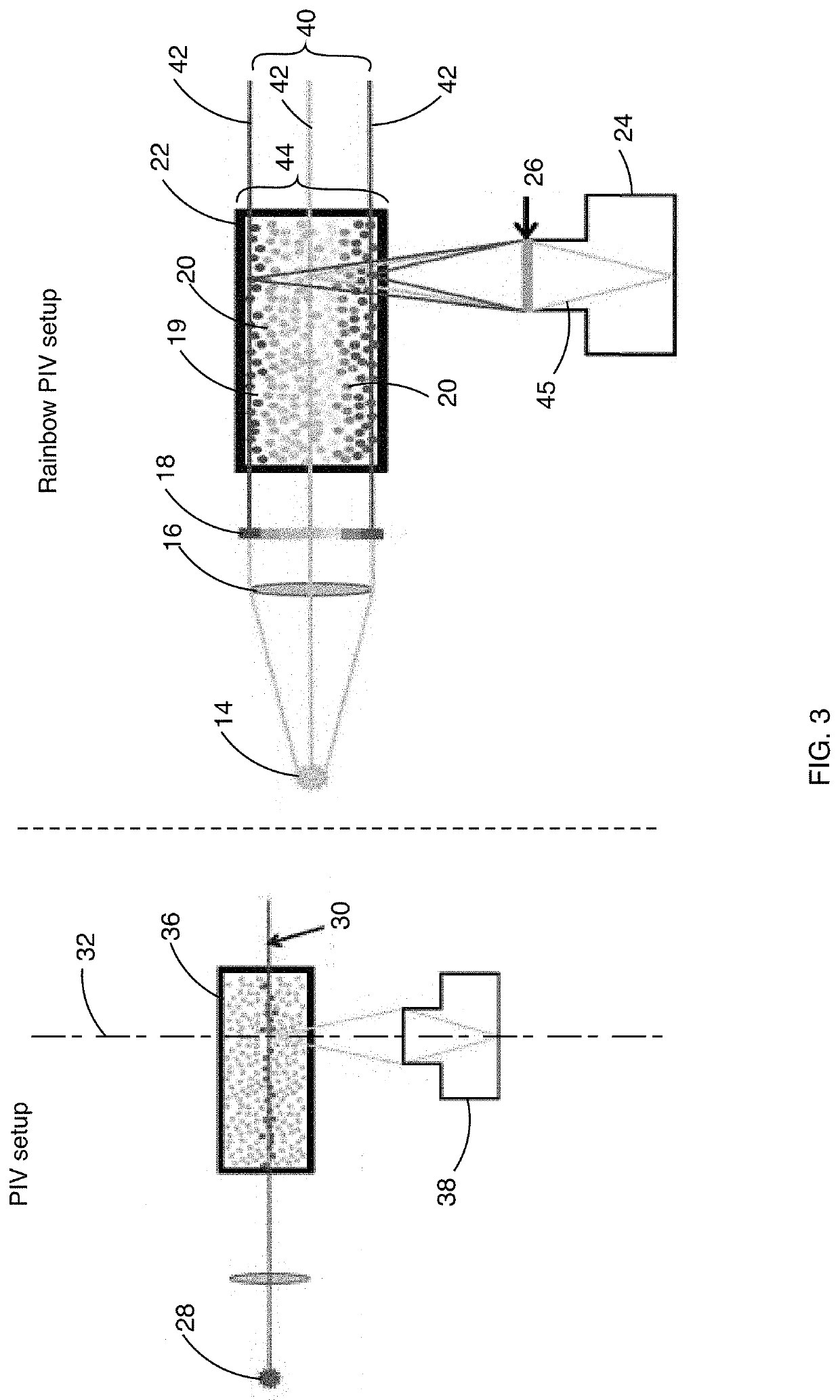
[0017]The detection means, which may in some cases be a camera, may in one aspect of the invention include a diffractive component in its optical structure to ensure that all of the light planes are in focus simultaneously. To facilitate this result, in one aspect of the invention, a diffractive optical element (DOE) may be attached to a camera's objective lens, in order to achieve a wavelength-selective focus that coincides with the rainbow illumination planes. The invention may thus provide a hybrid refractive-diffractive optical system, adapted to focus all wavelengths on the same sensor plane, thereby extending the depth-of-field, while preserving high lateral resolution, of the detection means. With this setup, for example, a single color camera may be sufficient to track 3D trajectories of particles by combining 2D spatial and 1D color information. Utilizing this setup, the reflection of light from different particles, having different wavelengths and hence indicating that the particles are positioned at different depths, may be focused on the sensor plane of the detection means.
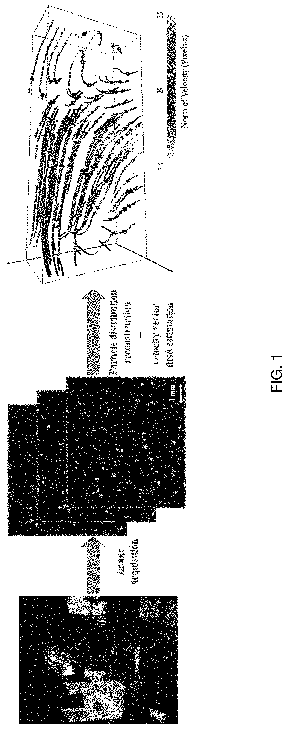
[0019]A further aspect of the invention may include a method for obtaining a three dimensional, three component velocity measurement of particles moving within a flow volume. The inventive method may combine a suitable setup for color-based encoding of the third dimension in the volumetric PIV, with a powerful algorithm to retrieve both the particle positions and the velocity vector field. For reconstruction, an image formation model for recovering stationary 3D particle positions may be provided. 3D velocity estimation may be achieved with a variant of 3D optical flow that accounts for both physical constraints as well as the rainbow image formation model. The reconstruction algorithm may utilize a detailed image formation model for this setup to retrieve the 3D location of particles in each frame. This may enable an integration of the temporal coherence regularization terms into the optical flow model, which may then be solved by a modular optimization framework. From a sequence of successively recorded frames, the velocity vector field may be reconstructed using an optical flow approach, where physical constraints (incompressible flow, temporal consistency of the flow) may be introduced. The inventive method therefore may introduce a physically constrained optical flow method for recovering the fluid velocity fields, and evaluating its effectiveness on synthetic data. The instant approach may therefore provide a good estimation of velocity over the measurement volume (high concentration of particles). In order to improve the obtained results, the user may iterate between position and velocity estimation, effectively solving a joint optimization problem for both.
[0025]A primary advantage of this approach, compared to other 3D PIV methods, is its simplicity. Nevertheless, the presence of random noise, optical aberrations and focus issues, color contamination caused by secondary light scattering from the particles, and color mixing for overlapping particles severely complicate the identification of the representative colors for every possible particle in the observed image.

Problems solved by technology

While these methods recover dense volumetric reconstructions, they only yield independent scalar fields of the density of the respective phenomenon at each time step.
While there have been efforts to recover velocities from the captured scalar fields through optical flow-style approaches, these attempts have been limited by the relatively small amount of high-frequency texture in the recovered data [Gregson et al.
2006] exist, a dense reconstruction of all three components of the velocity field over the full 3D volume requires multiple cameras and remains elusive in practice.
This requires some form of velocity estimation or flow tracking, which is difficult on this kind of input data.
The total number of cameras in these settings is usually very limited due to space constraints, as well as occlusions by solids, and is typically orders of magnitude lower than the number of projections in e-ray tomography, for example.
Another practical issue is depth of field of the cameras, since the whole volume needs to be in focus simultaneously and the camera aperture usually has to be large to collect enough light to capture fast flows.
Both of these approaches are in practice very hard to set up for many types of flow experiments.
However, due to the existence of ghost particles originated from reconstruction algorithm and reduced spatial resolution, it becomes difficult to reveal particle locations with relatively high accuracy.
Even though it revealed promising results for Particle Tracking Velocimetry (PTV), where low-density particles are seeded, it will fail for measuring a dense set of velocity fields, where sufficiently high density of particles is required.
Though significant improvements have been made on correlation methods [Stanislas et al 2008], they still have issues in areas of low particle density, which is common in 3D measurements.
2007], while most of them suffer from the complexity of solving higher order regularization terms.

Method used


Image

  • Rainbow particle imaging velocimetry for dense 3D fluid velocity imaging
  • Rainbow particle imaging velocimetry for dense 3D fluid velocity imaging
  • Rainbow particle imaging velocimetry for dense 3D fluid velocity imaging

Examples


example

Experimental setup: FIG. 2 illustrates the experimental setup configuration used to evaluate the performance of the Rainbow PIV setup and method.

[0082]Rainbow light generation: The experiments were performed using a high power plasma light source 14, combined with a liquid light guide (HPLS245, Thorlabs) to generate a white light (output spectrum: [390,730 nm]. A collimator 16 was added to obtain a parallel light beam. It is important to have a parallel light beam, to guarantee that two particles, having the same depth, will be illuminated by the same colored light, i.e. light having the same wavelength.

[0083]To split the white light into a rainbow beam, a continuously linearly varying bandpass filter (LF103245, Delta Optical Thin Film) was employed. Other alternatives such as a prism and blaze grating were also considered for this purpose in view of their respective ability to generate a rainbow beam. Although a bandpass filter was eventually selected for purposes of the invention,...


PUM


Abstract

Imaging of complex, non-stationary three dimensional (3D) flow velocities is achieved by encoding depth into color. A flow volume 22 is illuminated with a continuum 40 of light planes 42 whereby each depth corresponds to a respective light plane 14 having a specific wavelength of light. A diffractive component 46 in the camera 24 optics, which records the trajectories of illuminated particles 20 within the flow volume 22, ensures that all light planes 42 are in focus simultaneously. The setup permits a user to track 3D trajectories of particles 20 within the flow volume 22 by combining two dimensional (2D) spatial and one dimensional (1D) color information. For reconstruction, an image formation model for recovering stationary 3D particle positions is provided. 3D velocity estimation is achieved with a variant of a 3D optical flow approach that accounts for both physical constraints as well as the color (rainbow) image formation model.

Description

CROSS REFERENCE TO RELATED APPLICATIONS[0001]This application claims the benefit of U.S. Provisional Application 62 / 464,928 filed 28 Feb. 2017. This application further claims the benefit of U.S. Provisional Application 62 / 470,168 filed 10 Mar. 2017. The contents of these two Provisional applications are incorporated herein by reference in their entireties.FIELD[0002]This invention relates to fluid capture, particularly in the area of computer graphics. More specifically, the invention is directed to the imaging of complex, three dimensional flow velocities.STATE OF THE ART[0003]Fluid capture is an active research area in computer graphics. Despite significant recent progress, dense, time-resolved imaging of complex, non-stationary three dimensional (3D) flow velocities remains an elusive goal. Recent works include efforts to image phenomena such as flames [Hasinoff and Kutulaks 2007; Ihrke and Magnor 2004], smoke [Kawkins et al. 2005; Gu et al, 2013], transparent hot air flow [Atch...

Claims


Application Information

Patent Timeline
Patent Type & Authority Patents(United States)
IPC IPC(8): G01P3/36G01P5/20G06T11/00G01P5/00G01S17/58G01S11/12G01P5/26
CPCG01S11/12G01P5/001G01S17/58G06T11/00G01P5/26G01P5/20
Inventor HEIDRICH, WOLFGANGXIONG, JINHUIDUN, XIONGIDOUGHI, RAMZITHORODDSEN, SIGURDUR TRYGGVIAGUIRRE-PABLO, ANDRES A.ALJEDAANI, ABDULRAHMAN B.LI, ERQIANG
Owner KING ABDULLAH UNIV OF SCI & TECH
Learn More