
Thermally influenced changeable tint device

a technology of changeable tint and thermal influence, which is applied in the field of photochromic eyeglasses, can solve the problems of insufficiently satisfying the limitations of the day state of the art photochromic eyeglasses, the switching time of darkening is too slow and outdoors, and the photochromics never switch, etc., and achieves the effect of enhancing the performance of an opti

Active Publication Date: 2020-09-08
ESSILOR INT CIE GEN DOPTIQUE
View PDF29 Cites 3 Cited by
  • Summary
  • Abstract
  • Description
  • Claims
  • Application Information

AI Technical Summary

Benefits of technology

[0014]In one embodiment, the changeable tint element comprises a polymer layer. The heater causes the temperature of the polymer layer to be elevated above the glass transition temperature of the polymer for a period of time and then allows the temperature of the polymer layer to decrease below glass transition temperature of the polymer layer.
[0066]In one embodiment, a system for enhancing the performance of an optic is provided. The system includes an optic, a photochromic agent, a heating element, timer, and a sensor.

Problems solved by technology

Present day state of the art photochromic eyeglasses have still have numerous serious limitations which have not been properly satisfied even after 40 years or more of photochromic commercialization.
The problem is that, when in a form that is clear enough indoors, they never get dark enough outdoors and the switching time of darkening is too slow outdoors and too slow when switching to the clear state indoors.
In addition, photochromics never switch to a dark enough state behind the windshield of a car or other vehicle whereby the windshield filters out ultra-violet wavelengths of light.
There has always been a limiting performance balance with photochromatic optics and / or lenses.
The balance is the faster the darkening switch outdoors the more sensitive the photochromic optic and / or lens is to ambient heat or high temperature outdoors (which is exacerbated due to the sun's radiation) thus limiting the degree of darkening of the photochromic optic and / or lens and the speed in which it can darken.
This is due to both the increased cost of these photochromic eyeglasses and also the serious limitations which have been discussed above.
In addition, other electronic changeable tint devices have also lagged in commercial success and acceptance.
Changeable tint liquid crystal devices have met with limited commercial success due to the amount of electrical power needed to drive the devices over a period of time and also the lack of ability to shape post assembly these devices.
This is due to most, if not all, changeable tint liquid crystal devices not being electrically bi-stable and in addition once custom shaped after assembly suffering from the liquid crystal leaking out and compromising performance.
Finally, changeable tint electro-chromic devices have proven elusive in terms of acceptable performance contrast / dynamic range, ultra-fast switching time and power usage.

Method used


Image

  • Thermally influenced changeable tint device
  • Thermally influenced changeable tint device
  • Thermally influenced changeable tint device

Examples


tenth embodiment

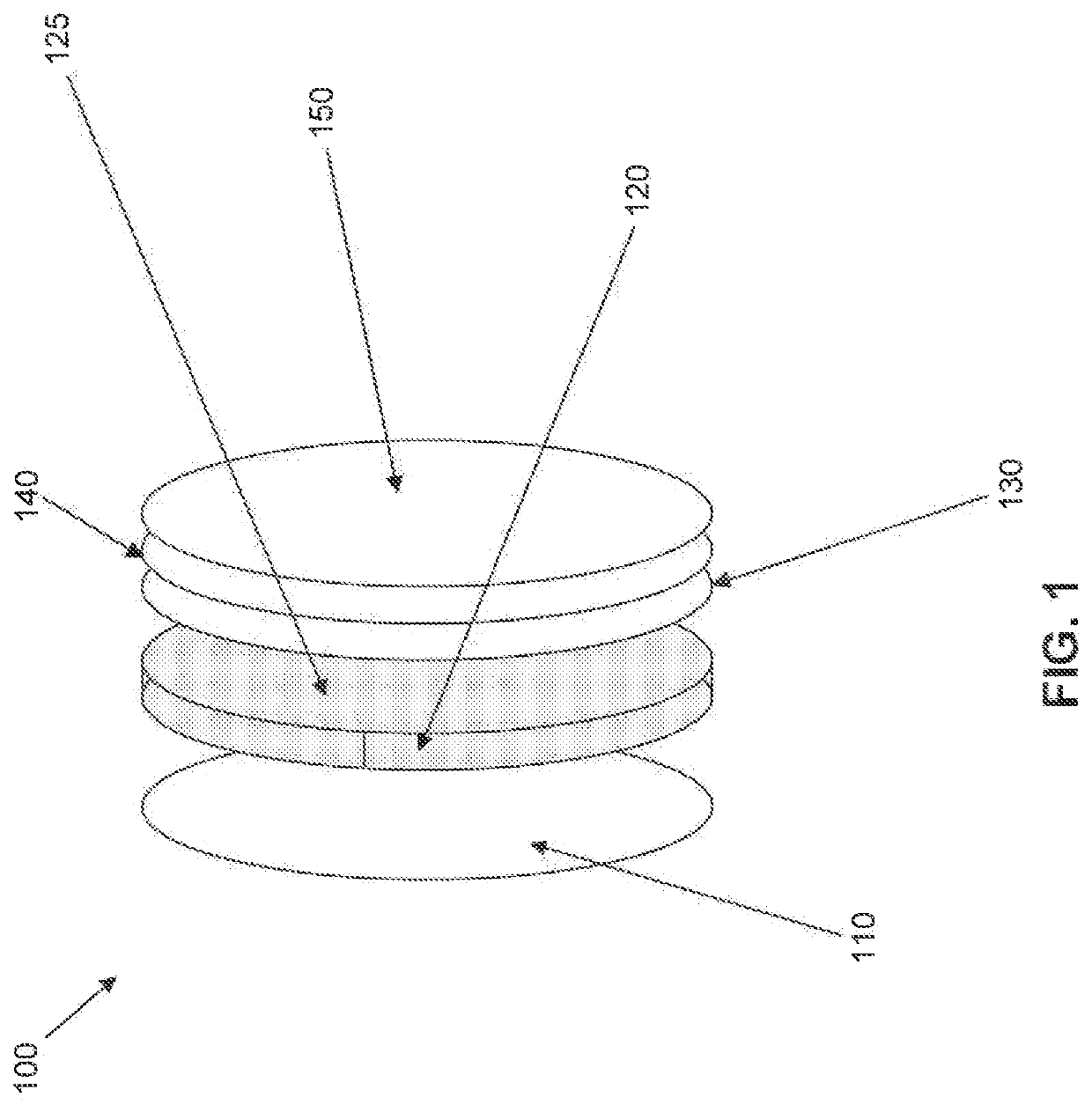
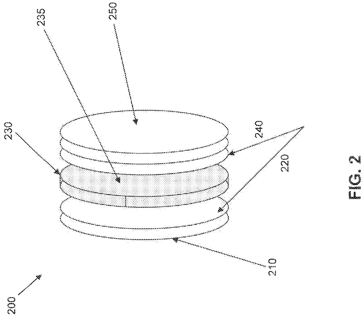
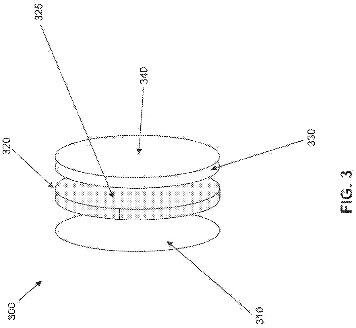
[0176]FIG. 17 shows a lens 1700 incorporating a cooling element, a heating element, an optic, and a photochromic layer. Lens 1700 includes, from the back of the lens (closest to the eye) to the front, a first anti-reflection coating layer 1705, a first hard coat layer 1710, an optic 1720, a second hard coat layer 1730, a cooling element 1740, a photochromatic layer 1750, a heating element 1760, a hard coat layer 1770 and a second anti-reflection coating layer 1780. Cooling element 1740 may have further layers, such as those illustrated in FIG. 16. FIG. 17 corresponds to the

eleventh embodiment

[0177]FIG. 18 shows a lens 1800 incorporating a thermally switchable polarized layer, a heating element, an optic, and a photochromic layer. Lens 1800 includes, from the back of the lens (closest to the eye) to the front, a first anti-reflection coating layer 1805, a first hard coat layer 1810, an optic 1820, a second hard coat layer 1830, a thermally switchable polarized layer 1840, a photochromatic layer 1850, a heating element 1860, a hard coat layer 1870 and a second anti-reflection coating layer 1880. FIG. 18 corresponds to the

[0178]Embodiments disclosed herein comprise a system which includes the photochromic optic or layer and associated electronics. While some embodiments disclosed herein discuss the optic or layer comprising a photochromic agent or agents being that of a polymer layer, such a layer or optic in certain embodiments could be that of glass. Some embodiments are a very elegant way to solve a pressing long term unmet need. It should be understood when the term op...

second embodiment

[0185]In a second embodiment a performance enhanced photochromic optic that comprises a heating element, by way of example only, that of a mostly transparent electrically enabled heated surface or layer is located close to or adjacent to a layer of material comprising a photochromic agent. The mostly transparent electrically enabled heated surface or layer is comprised of a layer, by way of example only, of thin glass or plastic having a heating element or member on its surface or buried within. The heating element or member can be that, by way of example only, of indium tin oxide which is capable of being energized or activated by the application of electricity and de-energized or de-activated by the removal of electricity. Any electrically conductive material (including that of a conductive polymer) can be used to make the heating element provided it meets the transparency needs for the performance of the optic. In a preferred embodiment the heating element is located on the side ...


PUM

PropertyMeasurementUnit
glass transition temperatureaaaaaaaaaa
temperatureaaaaaaaaaa

Abstract

A device is provided. The device includes a base ophthalmic optic, a changeable tint element disposed over the base ophthalmic element, and a transparent heating element adapted to heat the changeable tint element. The transparent heating element is preferably adapted to heat the entire area of the changeable tint element.

Description

BACKGROUND[0001]Present day state of the art photochromic eyeglasses have still have numerous serious limitations which have not been properly satisfied even after 40 years or more of photochromic commercialization. The problem is that, when in a form that is clear enough indoors, they never get dark enough outdoors and the switching time of darkening is too slow outdoors and too slow when switching to the clear state indoors. Further, when outdoors and in a high temperature environment the darkening effect becomes reduced. It is well known that the higher the ambient temperature environment the lower the photochromic absorption and or blocking effect.[0002]In addition, photochromics never switch to a dark enough state behind the windshield of a car or other vehicle whereby the windshield filters out ultra-violet wavelengths of light. It is known that photochromic eyeglasses absorb UV light and also in certain cases that of long wavelength blue light.[0003]There has always been a li...

Claims


Application Information

Patent Timeline
Patent Type & Authority Patents(United States)
IPC IPC(8): G02C7/10G02C11/08G02F1/01
CPCG02C7/102G02C7/101G02C11/08G02F1/0126
Inventor BLUM, RONALD D.
Owner ESSILOR INT CIE GEN DOPTIQUE
Learn More