Heat sink for an injection/metering valve

a technology of heat sink and injection/metering valve, which is applied in the direction of machines/engines, engine components, mechanical equipment, etc., can solve the problems of heat sink cooling behavior differences, exposed to high temperatures during operation,

Active Publication Date: 2020-09-08
ROBERT BOSCH GMBH
View PDF12 Cites 0 Cited by
  • Summary
  • Abstract
  • Description
  • Claims
  • Application Information

AI Technical Summary

Benefits of technology

[0010]In one embodiment, the baffle extends substantially at a right angle to the pipe segment. In this way, a precise geometry can be created, and the choice of angle at which the end of the pipe segment is beveled can be used to set a restricting effect of the inlet and / or of the outlet to a desired value with great accuracy.
[0011]In one embodiment, the heat sink has a receptacle for an injection / metering valve which is designed in such a way that the baffle extends substantially parallel to an injection / metering valve arranged in the receptacle. In this way, particularly uniform cooling of the injection / metering valve can be achieved.
[0012]In one embodiment, the coolant chamber is of substantially rotationally symmetrical design around the axis of an injection / metering valve arranged in the receptacle. A heat sink of rotationally symmetrical design can be produced in a particularly simple and economical manner.
[0013]In one embodiment, an axis of the pipe segment is aligned substantially at a right angle to an injection / metering valve arranged in the receptacle. In this way, it is possible to create a precise geometry, and the choice of angle at which the end of the pipe segment is beveled can be used to set the restricting effect of the inlet and / or of the outlet precisely to a desired value.
[0015]In one embodiment, the angle αzu of the pipe segment of the inlet is smaller than the angle αab of the pipe segment of the outlet. In this way, a sufficient coolant flow and hence sufficient cooling of the injection / metering valve can be achieved.
[0017]In one embodiment, the outlet is arranged opposite the inlet. In particular, the outlet is arranged opposite the inlet at an angle of 180° along the outer circumference of the heat sink. In this way, complete flow of coolant through the coolant chamber can be achieved.

Problems solved by technology

Here, the injection or metering valves are arranged directly on the exhaust line and are therefore exposed to high temperatures during operation.
Production tolerances of the heat sinks lead to different flow cross sections, resulting in a difference in the cooling behavior of the heat sinks.

Method used


Image

  • Heat sink for an injection/metering valve
  • Heat sink for an injection/metering valve

Examples


Embodiment Construction

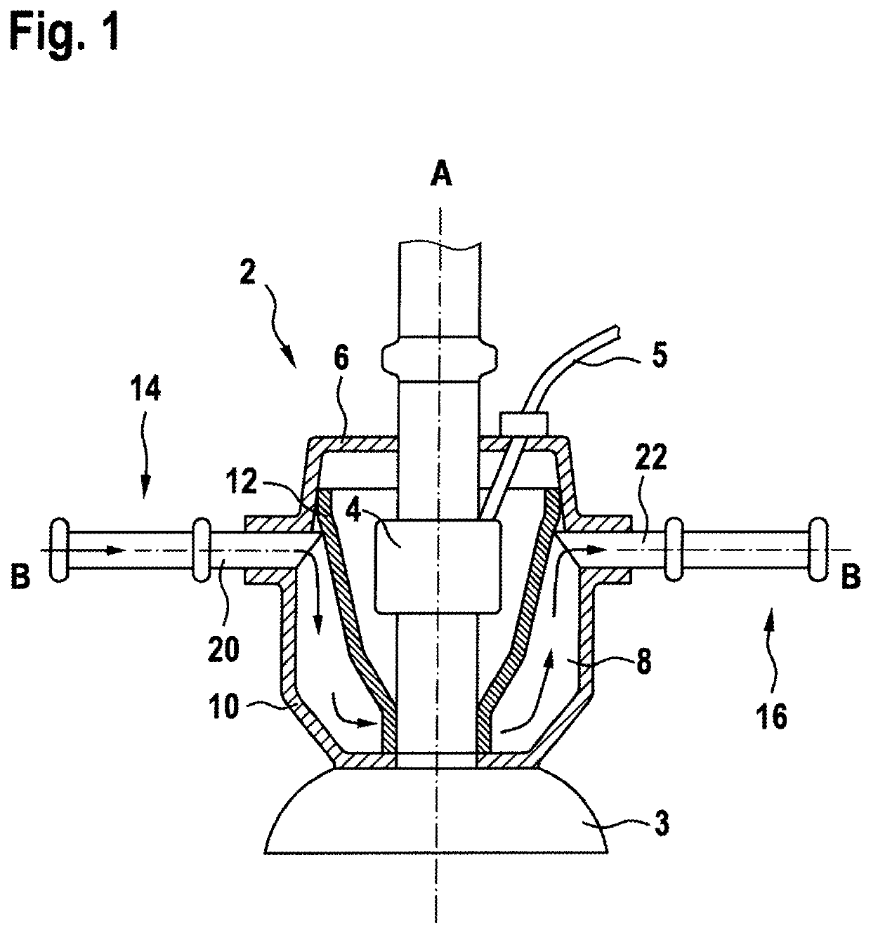
[0020]FIG. 1 shows a schematic section through a heat sink 2 having an injection / metering valve 4 according to one illustrative embodiment of the invention.

[0021]The heat sink 2 is arranged on an exhaust line 3 of an exhaust system of an internal combustion engine (not shown).

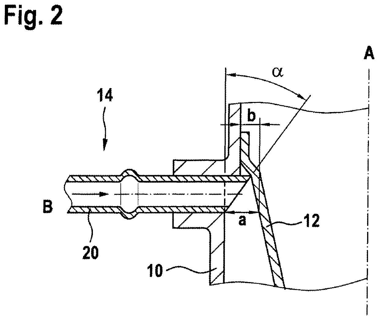
[0022]The heat sink 2 has a housing 6, which is formed in a substantially rotationally symmetrical manner around the axis A of the injection / metering valve 4 and in which a coolant chamber 8 is formed. The coolant chamber 8 is delimited on the outside by the wall 10 of the housing 6. At least one baffle 12 is arranged in the coolant chamber 8 and, in a region close to the exhaust line, which is illustrated in the lower part of FIG. 1, adjoins the outer circumference of the injection / metering valve 4.

[0023]An electric lead 5 for controlling the injection / metering valve 4 is passed into the interior of the housing 6 through a fluidtightly sealed opening in the housing 6.

[0024]Opening into the coolant chamber 8 ar...


PUM


Abstract

A heat sink (2) for an injection / metering valve (4) has a coolant chamber (8) which is designed for receiving a fluid coolant. The coolant chamber (8) has at least one inlet (14) for supplying the coolant and at least one outlet (16) for removing the coolant. The at least one inlet (14) and / or outlet (16) has a pipe segment (20, 22) which extends with one end into the coolant chamber (8). The coolant-chamber-side end of the pipe segment (20, 22) is bevelled, and therefore the coolant-chamber-side end of the pipe segment (20, 22) is in contact at at least one point along its circumference with a baffle (12) arranged in the coolant chamber (8), and the end of the pipe segment (20, 22) is spaced apart at another point along its circumference from the baffle (12).

Description

BACKGROUND OF THE INVENTION[0001]The invention relates to a heat sink for an injection or metering valve.[0002]In systems for exhaust gas aftertreatment, injection or metering valves are used to inject a fluid reducing agent, e.g. an aqueous urea solution (“AdBlue”®), into the exhaust line of an internal combustion engine, in particular of a diesel engine. Here, the injection or metering valves are arranged directly on the exhaust line and are therefore exposed to high temperatures during operation.[0003]In order to avoid damage to the injection / metering valves and to ensure reliable operation, the injection / metering valves are often provided with heat sinks, through which a fluid coolant flows in order to cool the injection / metering valve.[0004]Production tolerances of the heat sinks lead to different flow cross sections, resulting in a difference in the cooling behavior of the heat sinks.SUMMARY OF THE INVENTION[0005]It is an object of the invention to make available heat sinks fo...

Claims


Application Information

Patent Timeline
Patent Type & Authority Patents(United States)
IPC IPC(8): F01N3/00F01N3/20
CPCF01N3/2066F01N2610/1453F01N2610/11F01N2610/02Y02T10/12
Inventor HANNEKE, JUERGEN
Owner ROBERT BOSCH GMBH
Why Eureka
Try Eureka