Projection device
a projection device and projection technology, applied in the direction of picture reproducers using projection devices, semiconductor lasers, instruments, etc., can solve the problems of reducing the light output time, affecting the color unevenness of the light caused by the difference in occurrence of light emission delay between and reducing the light amount resulting from the light emission delay at the start of light emission of the light emitting elements. , to achieve the effect of suppressing or preventing problems
- Summary
- Abstract
- Description
- Claims
- Application Information
AI Technical Summary
Benefits of technology
Problems solved by technology
Method used
Image
Examples
first embodiment
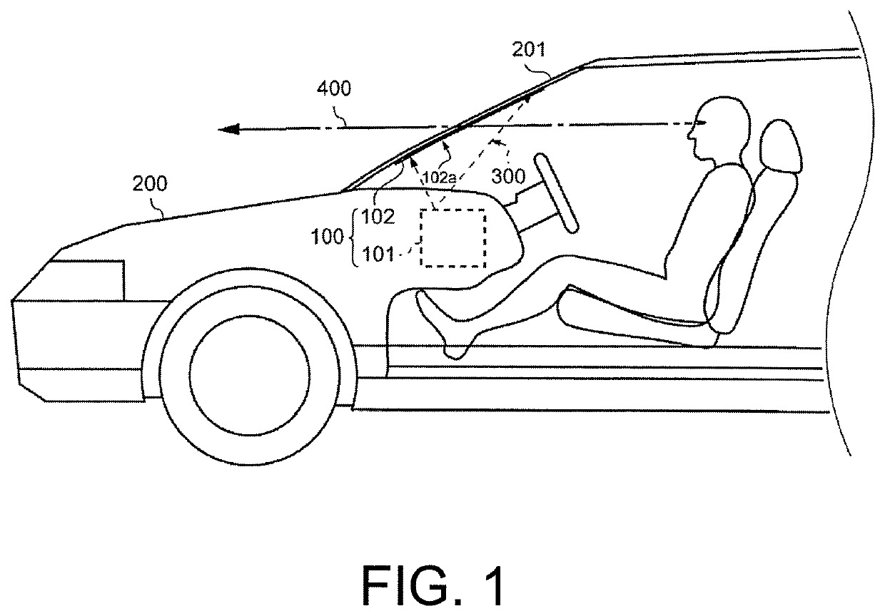
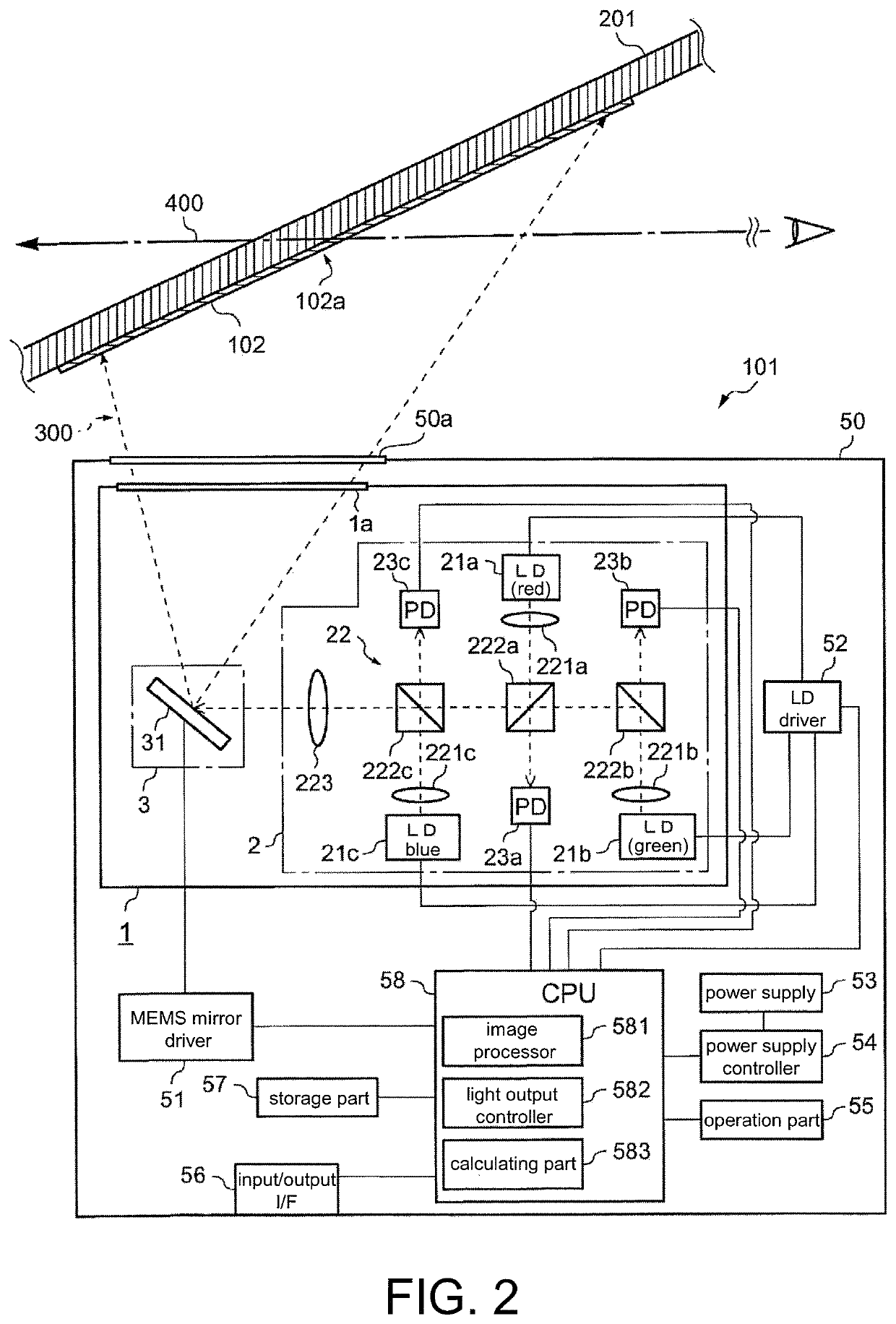
[0068]FIG. 1 is a schematic diagram of the HUD device 100. The HUD device 100 of this embodiment is installed in a vehicle 200. The HUD device 100 is a display device that projects a scanning laser light 300 (scanning light) from a projector unit 101 (light projection device) to a combiner 102 and overlaps a projection image thereof in a field of view of the user to display it. In FIG. 1, a dashed line arrow 400 indicates a sight line of the user who is sitting in a driver's seat of the vehicle 200. Moreover, the HUD device 100 is not necessarily installed in the vehicle and may also be installed in other means of transportation (such as an airplane and so on).
[0069]The combiner 102 is attached to an inner surface of a windshield 201 of the vehicle 200, as shown in FIG. 1. The combiner 102 is a projection member for displaying the projection image of the projector unit 101 in the user's field of view and is formed by using a semi-transmissive reflective material, such as a half mirr...
embodiments
[0103]Then, the embodiments are described. FIG. 8 is a graph showing an example of the light output control of the LD 21a-21c according to the first embodiment. In addition, FIG. 9 is a schematic diagram showing an example of the light output of the scanning laser light 300 when light output control is performed according to the first embodiment.
[0104]As shown in FIG. 8, in this embodiment, when the image is formed by the light outputs of the LD 21a-21c, the driving currents Ia1, Ib1, and Ic1 are applied to the LD 21a-21c such that the times ta1, tb1, and tc1 (=tc0) when the LD 21a-21c respectively reach the constant light amounts Pa1, Pb1, and Pc1 corresponding to the driving currents Ia1, Ib1, and Ic1 are the same. That is, the light output controller 582 sets the time ta0 when application of the driving current to the LD 21a having the longest rising time TA among the LD 21a-21c starts to be earlier than the times tb0 and tc0 when application of the driving currents to the other ...
second embodiment
[0107]The second embodiment is described hereinafter. In the second embodiment, the light output controller 582 performs light output control over the LD 21a-21c such that the times ta2, tb2, and tc2 (=tc0) when the LD 21a-21c respectively reach half of the constant light amounts (i.e., 0.5Pa, 0.5Pb, and 0.5Pc) are the same. Otherwise, the second embodiment is the same as the first embodiment. The configuration different from that of the first embodiment is described hereinafter. In addition, components the same as those of the first embodiment are assigned with the same reference numerals, and descriptions thereof are omitted.
[0108]FIG. 10 is a graph showing an example of the light output control of the LD 21a-21c according to the second embodiment. FIG. 10 illustrates the response characteristics of the light outputs of the LD 21a-21c when the LD 21a-21c perform white display from the state of the light amount 0, for example. As shown in FIG. 10, the time ta0 when the driving curr...
PUM
| Property | Measurement | Unit |
|---|---|---|
| transmittance | aaaaa | aaaaa |
| scanning distance | aaaaa | aaaaa |
| oscillation threshold current | aaaaa | aaaaa |
Abstract
Description
Claims
Application Information
 - R&D
- Intellectual Property
- Life Sciences
- Materials
- Tech Scout
- Unparalleled Data Quality
- Higher Quality Content
- 60% Fewer Hallucinations
Browse by: Latest US Patents, China's latest patents, Technical Efficacy Thesaurus, Application Domain, Technology Topic, Popular Technical Reports.
© 2025 PatSnap. All rights reserved.Legal|Privacy policy|Modern Slavery Act Transparency Statement|Sitemap|About US| Contact US: help@patsnap.com


