
Circuit card assemblies for a communication system

a technology of circuit card and communication system, which is applied in the direction of electrical apparatus, connection, coupling device connection, etc., can solve the problems of limiting operating speed, overheating of components, and high cost of electrical connectors to manufactur

Active Publication Date: 2020-08-11
TYCO ELECTRONICS LOGISTICS AG (CH) +1
View PDF64 Cites 2 Cited by
  • Summary
  • Abstract
  • Description
  • Claims
  • Application Information

AI Technical Summary

Benefits of technology

The patent text describes a communication system that includes two circuit card assemblies that are mated together. The first circuit card assembly has a first PCB with first contacts and a first electrical connector mounted on it. The second circuit card assembly has a second PCB with second contacts and a second electrical connector mounted on it. The first and second PCBs are mated together by loading the second PCB into the first slot in a board loading direction. The technical effect of this design is that it allows for a more efficient and secure connection between the two circuit card assemblies.

Problems solved by technology

However, such backplanes or midplanes block airflow through the communication system leading to overheating of components or limiting operating speeds to avoid overheating.
However, such right angle electrical connectors are expensive to manufacture and occupy a large amount of space in the system, thus blocking airflow through the system.
Furthermore, adding density to the system in the form of a greater number of signal contacts increases the size of the connector in at least one direction, further blocking airflow through the system.

Method used


Image

  • Circuit card assemblies for a communication system
  • Circuit card assemblies for a communication system
  • Circuit card assemblies for a communication system

Examples


Embodiment Construction

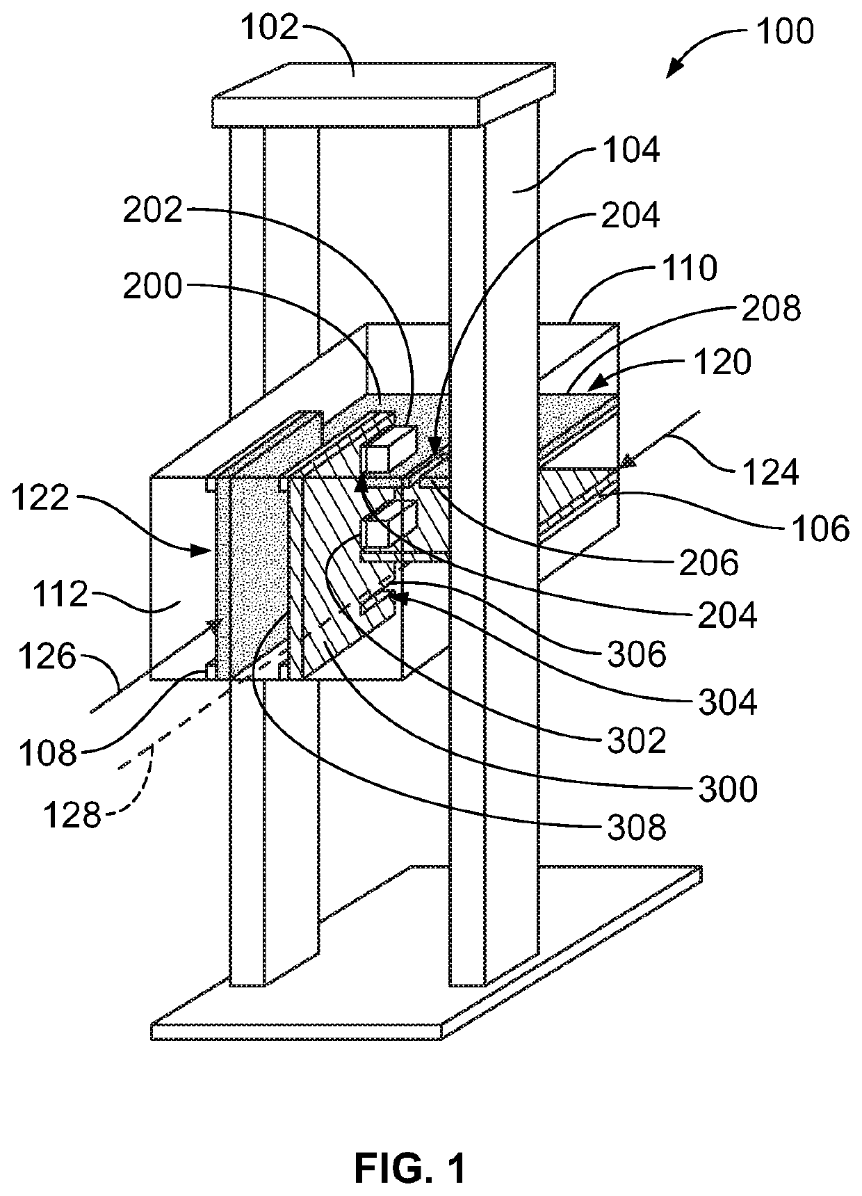
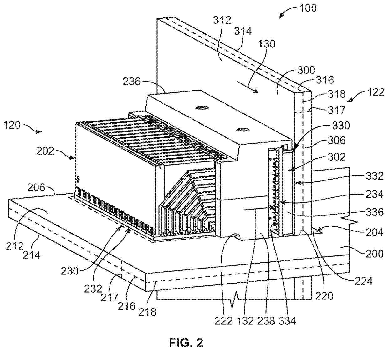
[0026]FIG. 1 illustrates a communication system 100 formed in accordance with an exemplary embodiment. The communication system 100 includes a chassis 102 having a frame 104 configured to hold communication components, such as network components, such as circuit card assemblies. Optionally, the chassis 102 may include a cabinet (not shown) surrounding components of the communication system 100. In an exemplary embodiment, the frame 104 includes a plurality of racks 106, 108 for holding circuit card assemblies. For example, the communication system 100 may form part of a data center switch having one or more backplanes and / or daughter cards, such as line cards, switch cards or other types of circuit cards that may be electrically connected together.

[0027]In an exemplary embodiment, the communication system 100 includes a front end 110 and a rear end 112. The racks 106 are provided at the front end 110 and the racks 108 are provided at the rear end 112. One or more circuit card assemb...


PUM


Abstract

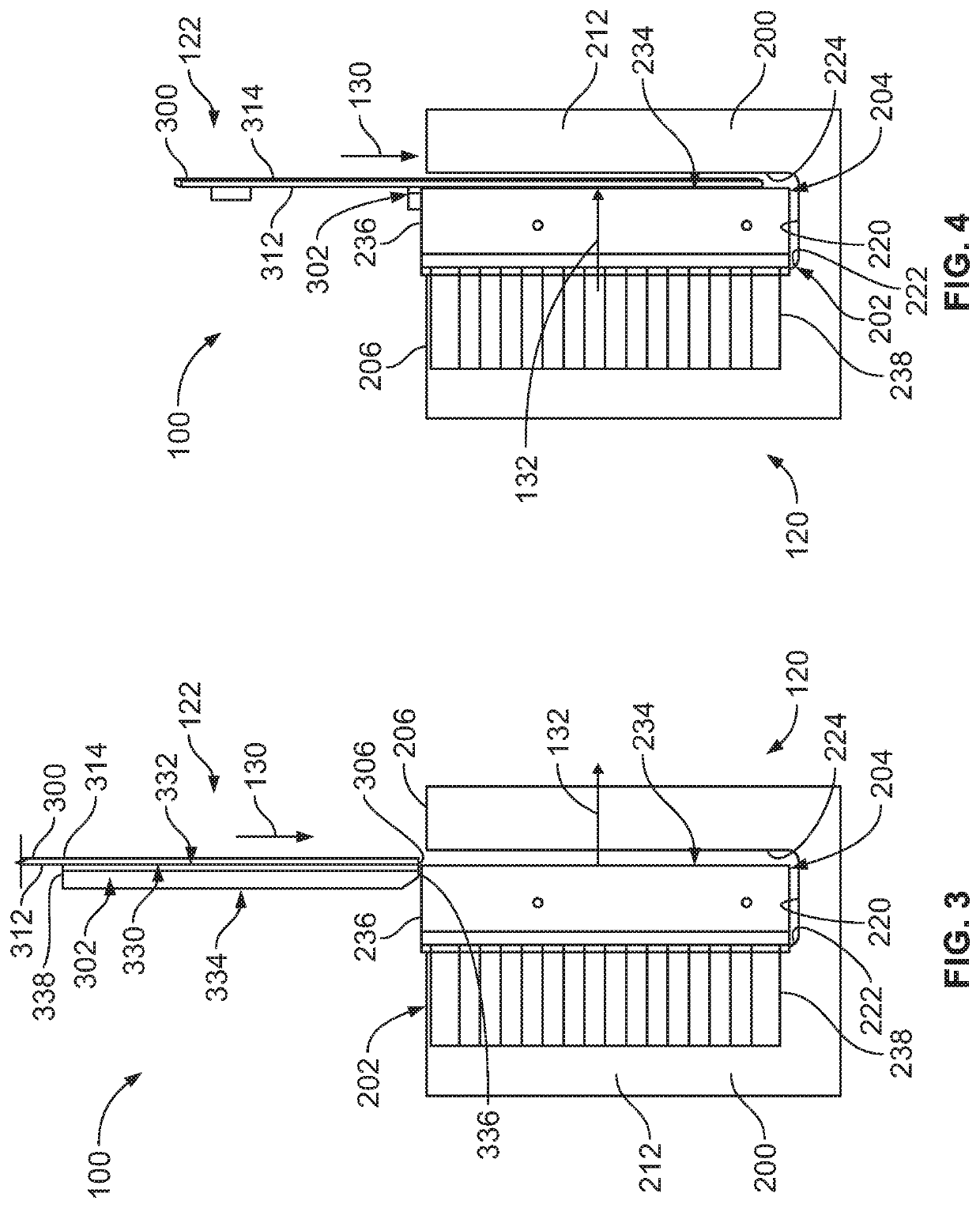
A communication system includes first and second circuit card assemblies mated such that first and second PCBs move relative to each other along a board mating axis parallel to a slot in the first PCB with the first PCB oriented perpendicular to the second PCB and with first and second mating ends of first and second electrical connectors oriented parallel to the board mating axis. The first and second circuit card assemblies are mated such that the first electrical connector and the second electrical connector move relative to each other along a connector mating axis perpendicular to the board mating axis. Mating interfaces the contacts are oriented at contact mating angles non-parallel to the board loading axis and non-parallel to the connector mating axis.

Description

BACKGROUND OF THE INVENTION[0001]The subject matter herein relates generally to circuit card assemblies for communication systems.[0002]Communication systems are in use in various applications, such as network switches. The communication systems include various circuit cards, such as backplanes and / or daughtercards, which are coupled together to electrically connect various circuits. For example, the circuit cards include electrical connectors that are mated to electrical connectors of one or more other circuit cards. Some communication systems use a backplane or midplane that is perpendicular to the mating direction of the daughtercards. However, such backplanes or midplanes block airflow through the communication system leading to overheating of components or limiting operating speeds to avoid overheating.[0003]Other communication systems arrange both circuit cards parallel to the mating direction to allow airflow through the system. The circuit cards are typically oriented perpen...

Claims


Application Information

Patent Timeline
IPC IPC(8): H01R12/73H01R12/72H01R12/71
CPCH01R12/712H01R12/727H01R12/737H05K2201/04H01R12/716H01R13/518
Inventor CONSOLI, JOHN JOSEPHMORGAN, CHAD WILLIAMSHIRAI, HIROSHI
Owner TYCO ELECTRONICS LOGISTICS AG (CH)
Learn More