
Compact centrifugal apparatus for conveying a fluid

a centrifugal apparatus and fluid technology, applied in the direction of radial flow pumps, non-positive displacement fluid engines, pump components, etc., can solve the problems of increasing the size of the fan blades and motors, and achieve the effect of increasing pressure and pressur

Active Publication Date: 2020-08-11
FARMER HANNAH +1
View PDF3 Cites 0 Cited by
  • Summary
  • Abstract
  • Description
  • Claims
  • Application Information

AI Technical Summary

Benefits of technology

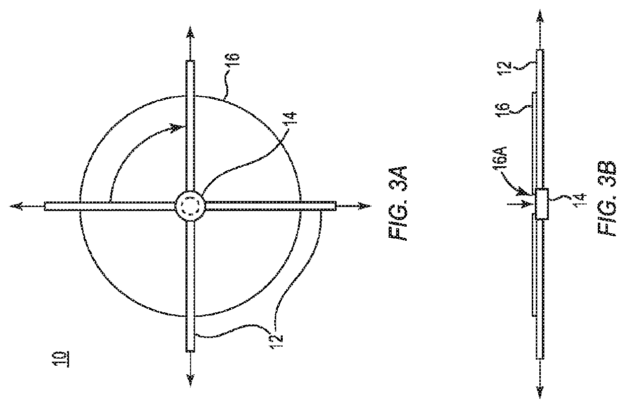
[0006]There is provided a radically new type of centrifugal flow device having a preferred use, but not necessarily limited to, in a hovercraft, in which the flow increases faster than increases in RPM (unlike in traditional centrifugal devices) and moves more air and produces higher pressures than ordinary centrifugal pumps. It has been discovered that a centrifugal flow pump device has flow that increases superlinearly with increased revolutions per minute (RPM) of the device using, but not necessarily limited to, a set of substantially cylindrical tubes disposed about a round plate or disk. In one example embodiment, the tubes are disposed at the 90, 180, 270 and 360 degree positions (or 12, 3, 6 and 9 o'clock positions on a clock) with the inlets of the tubes disposed at an inlet manifold at the interior of the disk and the outlet of the tubes disposed at the outer edge of the disk. This effect can be used to make a more compact pump, for a hovercraft for example, that moves more air and produces higher pressures than ordinary pumps.
[0008]In one example embodiment, there is provided an improved centrifugal airflow pump assembly that includes an inflow rotating impeller device including a substantially circular base member supporting a plurality of individual fluid channel members disposed along radii on a top surface of the base member, wherein an inlet of the fluid channel members is configured to be exposed to a fluid flowing through the channel members. The airflow pump assembly also includes a rotating mechanism coupled to the base member of the impeller device at a center point of a bottom surface of the base member to facilitate axial movement of the base member, the rotating mechanism rotating the base member and fluid channel members at a defined rate of revolutions per minute (RPM), wherein an increase of a flow rate of fluid exiting an outlet of the fluid channel members is faster than an increase in RPM (superlinear), and wherein the increased exiting fluid flow is a function of the structure of each of the plurality of the fluid channel structures and exposure of the inlets to the fluid flowing through the channel members. In a related embodiment, all of the fluid channel members do not all have to be axially equidistant from each other and the fluid is not limited to air. Some of the fluid channel structures can have one separation distance and some can have another distance. In a preferred embodiment, the channel structures appear to exhibit improved performance when along a radius of a circular support disc.

Problems solved by technology

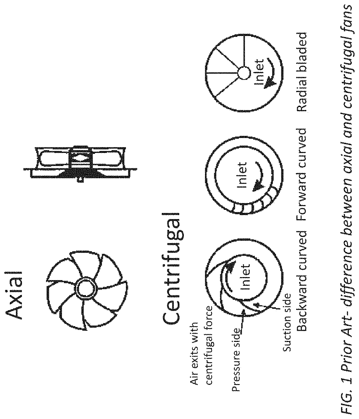
With both designs, in order to move more air and increase pressures, the size of the fan blades and motor have to increase which in some applications would be undesirable where space is at a premium.

Method used


Image

  • Compact centrifugal apparatus for conveying a fluid
  • Compact centrifugal apparatus for conveying a fluid
  • Compact centrifugal apparatus for conveying a fluid

Examples


example one

[0037]Measurements were taken of the flow through the hole in the plastic disc at different spinning speeds for different tube diameters and different tube lengths using combinations from the following table (over 200 measurements in total). Prior to each flow measurement, the rotational speed was determined and recorded using a tachometer.

[0038]

Tube diametersTube lengthsRotational speeds0.317 cm2.94cmdrill0.635 cm5.87cm620 to 3000 RPM usingdrill press0.794 cm11.7cm>3000 RPM using Dremel29.5cm

[0039]Each measurement was repeated 3 times. To test the underlying cause of the rapid (superlinear) increase in flow with rotational speed, a test system was built using cones instead of straight tubes, then the flow through these cones was measured as a function of RPM.

[0040]Considering the following variables:

Dependent Variable:

[0041]Air flow (liters / min).

Independent Variables:

[0042]Tube length (4 different lengths), tube diameter (or area, 3 different values), rotational speed (ranging from...


PUM


Abstract

An improved centrifugal pump uses straight tubes or fluid channel members rather than expanding passages between the inlet and exit flow. In straight tubes a process occurs of building up of pressure faster than within the passages as the fluid attempts to expand due to the Coriolis force potentially acting against the centrifugal force to build up the pressure within and along the tube or fluid channel. Because the flow increases faster than increases in RPM a more compact pump is provided that can move more air and produce higher pressures than ordinary centrifugal pumps. Hence: 1) Flow increases proportional to tube area because a larger area means more air can be drawn into the tube; 2) Flow increases proportional to tube length because the exit pressure increases proportional to tube length; and 3) Flow increases faster than increases in RPM, thereby exhibiting a higher outflow pressure.

Description

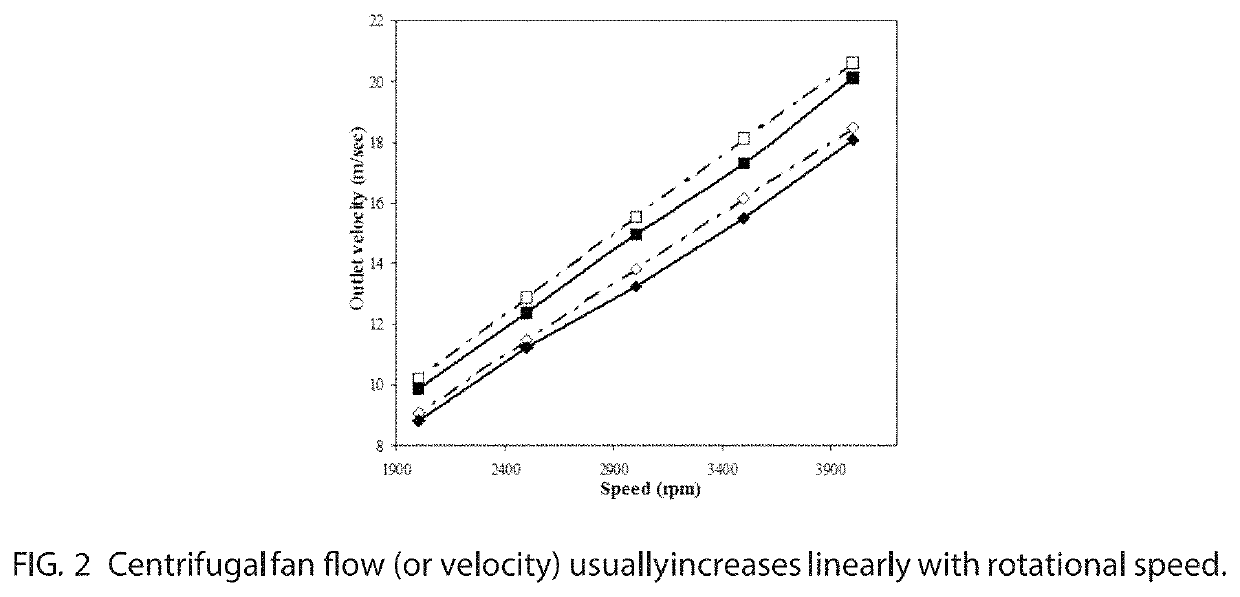
CLAIM OF PRIORITY[0001]This application claims the benefit of and priority to U.S. Provisional Application with Ser. No. 62 / 505,599, filed on May 12, 2017, with the same title, the contents of which are hereby incorporated by reference in its entirety.FIELD OF THE INVENTION AND BACKGROUND[0002]The invention is generally in the field of centrifugal pumps and fluid flow devices.[0003]In the field of pumps and fans, there are generally two types: axial and centrifugal. As illustrated in FIG. 1, in axial devices flow is along the axis, while in centrifugal devices flow enters through a central inlet and exits perpendicular to the inlet flow due to centrifugal force. The volume between centrifugal fan blades usually expands out from the inlet to the exit. As shown in FIG. 2, a classic property of centrifugal fans is that the fan flow usually increases proportional to rotational speed. With both designs, in order to move more air and increase pressures, the size of the fan blades and moto...

Claims


Application Information

Patent Timeline
Patent Type & Authority Patents(United States)
IPC IPC(8): F04D29/28F04D17/08F04D29/22
CPCF04D29/281F04D29/28F04D17/08F04D29/2255F04D29/225
Inventor FARMER, HANNAHFARMER, KENNETH
Owner FARMER HANNAH
Learn More