
Apparatus for increasing flow rate in engine pipe and processing method therefor

a technology of flow rate and engine, which is applied in the direction of machines/engines, combustion-air/fuel-air treatment, other domestic articles, etc., can solve the problems of deterioration in output, difficult smooth exhaustion of combustion gas, increase of fuel cost, etc., to maximize the flow length, the effect of maximizing the circular flow length

Active Publication Date: 2020-08-11
KIM GIHUN
View PDF21 Cites 0 Cited by
  • Summary
  • Abstract
  • Description
  • Claims
  • Application Information

AI Technical Summary

Benefits of technology

The present invention provides a flow rate increasing tube for gas flow that has inner and outer parts for a circular flow, which maximize the flow length and minimize flow resistance. The tube also has a cut-out part that prevents gas collision. The tube body fixing plate is easy to install. The technical effect of this invention is a more efficient and smooth gas flow without vortex loss.

Problems solved by technology

However, the exhaust pipe through which the combustion gas passes consists of a simple circular linear pipe and thus the exhaust resistance is directly applied into the inside of the exhaust pipe thereby making a smooth exhaustion of the combustion gas difficult and raising problems such as deterioration in output, increase of fuel cost, loss of engine power itself, etc.
However, it was configured such that the combustion gas, that passes through the inside of the exhaust pipe, collides with the rifling and turn along the spring and it only generated a very weak circulation phenomenon.

Method used


Image

  • Apparatus for increasing flow rate in engine pipe and processing method therefor
  • Apparatus for increasing flow rate in engine pipe and processing method therefor
  • Apparatus for increasing flow rate in engine pipe and processing method therefor

Examples


Embodiment Construction

Technical Problem

[0008]As such, the present invention is to solve the problems of the apparatus for increasing the flow rate installed in the inhalation pipeline or exhaust pipeline in that the circulation flow of a gas is not defined and does not occur actively and thus the mixing of fuels and the release of the exhaust gas cannot be smoothly performed and the installation cannot be easily made.

Technical Solution

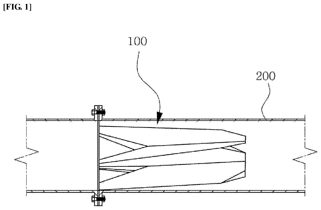
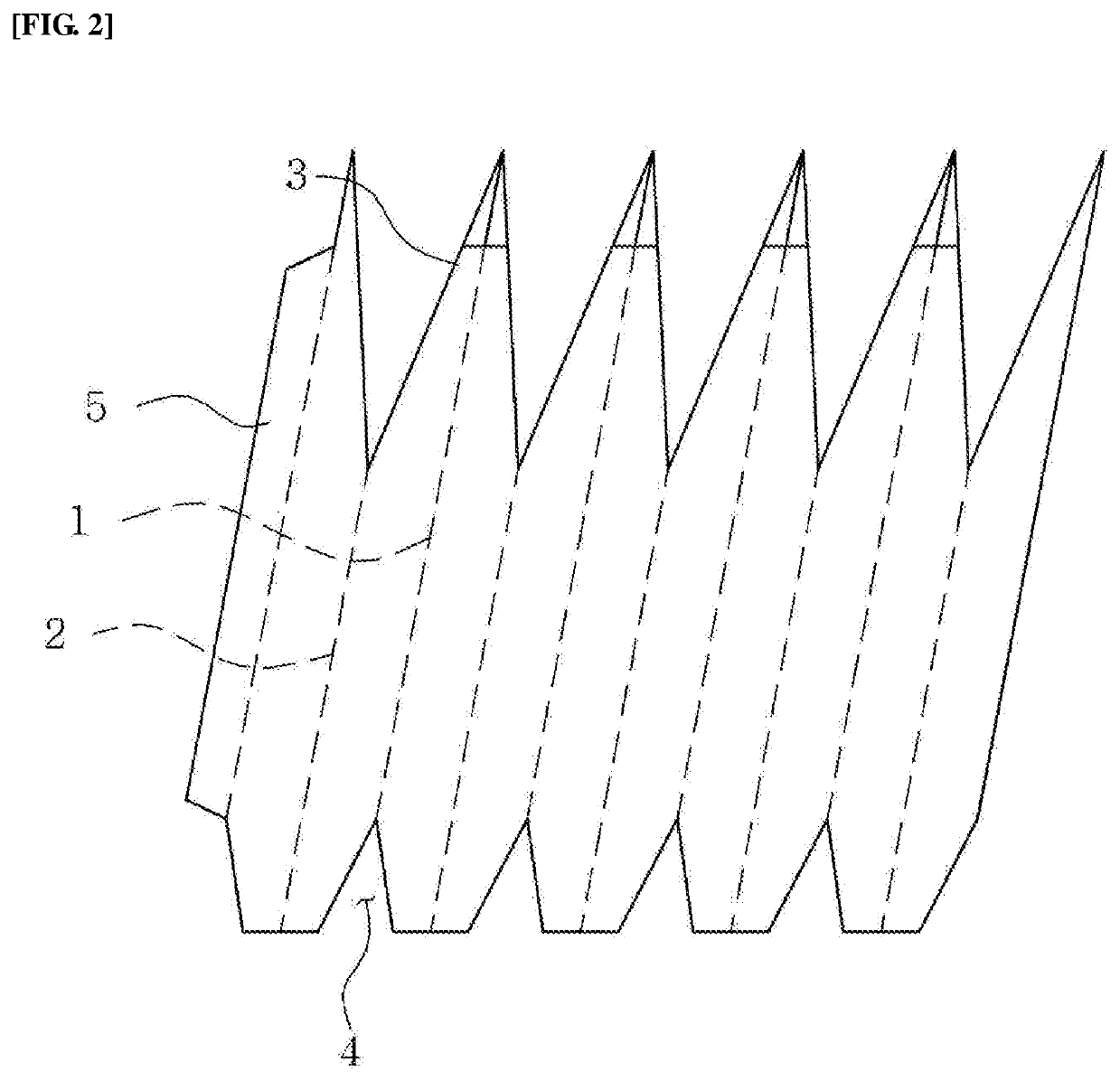
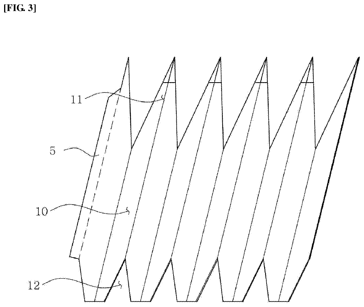
[0009]That is, the present invention relates to an apparatus for increasing a flow rate in an engine pipe and a method of processing the same and, more specifically, to an apparatus for increasing the flow rate in an engine pipe, in which the apparatus for increasing the flow rate in an engine pipe includes: a flow rate increasing tube body, in which an elastic board, whose inner diameter is configured to be narrowed toward the direction of a gas flow, is formed by bending; an inner part for a circular flow, which, being comprised of circular flow inducing grooves formed by...


PUM

PropertyMeasurementUnit
flow rateaaaaaaaaaa
heightaaaaaaaaaa
depthaaaaaaaaaa

Abstract

The present invention relates to an apparatus for increasing the flow rate in an engine pipe, and a processing method therefor and, more specifically, to an apparatus for increasing the flow rate in an engine pipe, the apparatus being provided in an engine pipe so as to define a circular flow of a gas by maximizing a circular flow length of the flowing gas, enabling the gas to flow circularly along an outer surface of a flow rate increasing tube body, preventing the occurrence of a vortex due to the collision of the gas flowing in the inside and the outside of the flow rate increasing tube body, and preventing the occurrence of noise and the like since the flow rate increasing tube body is firmly fixed to the pipe.

Description

TECHNICAL FIELD[0001]The present invention relates to an apparatus for increasing a flow rate in an engine pipe and a method of processing the same and, more specifically, to an apparatus for increasing the flow rate in an engine pipe, in which the apparatus for increasing the flow rate in an engine pipe includes: a flow rate increasing tube body, in which an elastic board, whose inner diameter is configured to be narrowed toward the direction of a gas flow, is formed by bending; an inner part for a circular flow, which, being comprised of circular flow inducing grooves formed by bending in a helical form is provided at equal intervals so as to circularly flow an air introduced into the inside of the flow rate increasing tube body; a part for inducing gas introduction, in which a circular flow inducing groove is extendedly formed toward a gas inlet, so as to induce the circular introduction of a gas to a side of the gas inlet of the inner part for a circular flow and maximize a circ...

Claims


Application Information

Patent Timeline
Patent Type & Authority Patents(United States)
IPC IPC(8): B21D5/16F02B31/04F01N1/12B21D53/04B21D51/06F15D1/02F02M35/10F01N13/00
CPCF02M35/10B21D53/04F01N13/00F02M35/10262F01N1/12F02B31/04F01N13/007B21D51/06F15D1/02B21D5/16Y02T10/12F01N2260/06B21D5/00B23P15/00F01N13/08F02M35/10091F02M35/104B23P2700/50
Inventor KIM, GIHUN
Owner KIM GIHUN
Learn More