
Fuel injection control device

a control device and fuel injection technology, applied in the direction of electric control, machines/engines, instruments, etc., can solve the problems of increasing the risk of the above-mentioned misfire, the minimum amount of injection allowing partial lift increases undesirably, and the misfire is caused undesirably, so as to increase the concern

Active Publication Date: 2020-08-04
TOYOTA JIDOSHA KK
View PDF19 Cites 0 Cited by
  • Summary
  • Abstract
  • Description
  • Claims
  • Application Information

AI Technical Summary

Benefits of technology

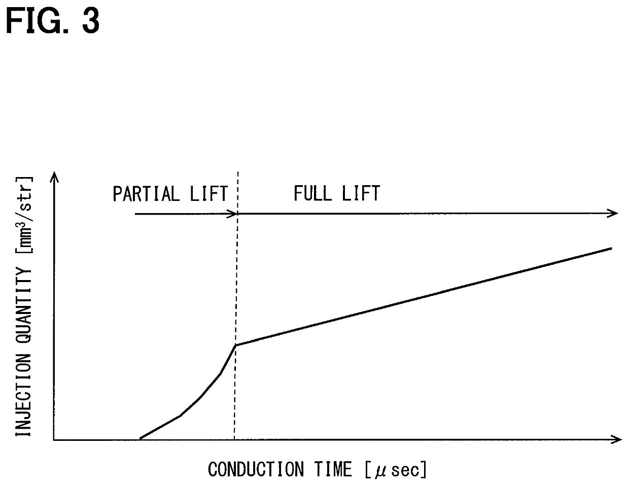
The present invention relates to a fuel injection control device that aims to minimize the amount of fuel injected during partial lift injection without increasing the risk of misfire. This is achieved by providing a lower limit time for valve opening that is close to the misfire limit time, which prevents misfires from occurring. Basically, the device controls the injection in a way that reduces the minimum quantity of fuel needed for the engine to operate without misfiring during partial lift injection.

Problems solved by technology

On this occasion, since the valve body is not shifted to valve opening, a fuel is not injected and misfire is caused undesirably.
If a lower limit time is set at an excessively high level, a minimum injection quantity allowing partial lift injection increases undesirably.
If a lower limit time is set at an excessively low level, a risk of the aforementioned misfire increases undesirably.

Method used


Image

  • Fuel injection control device
  • Fuel injection control device
  • Fuel injection control device

Examples


first embodiment

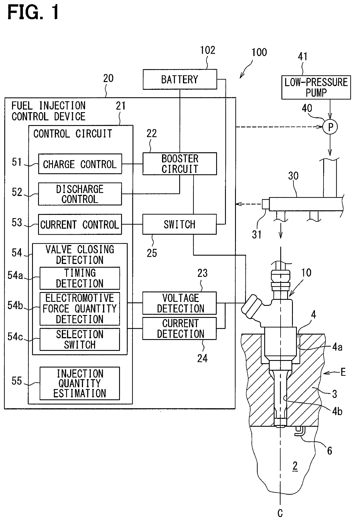
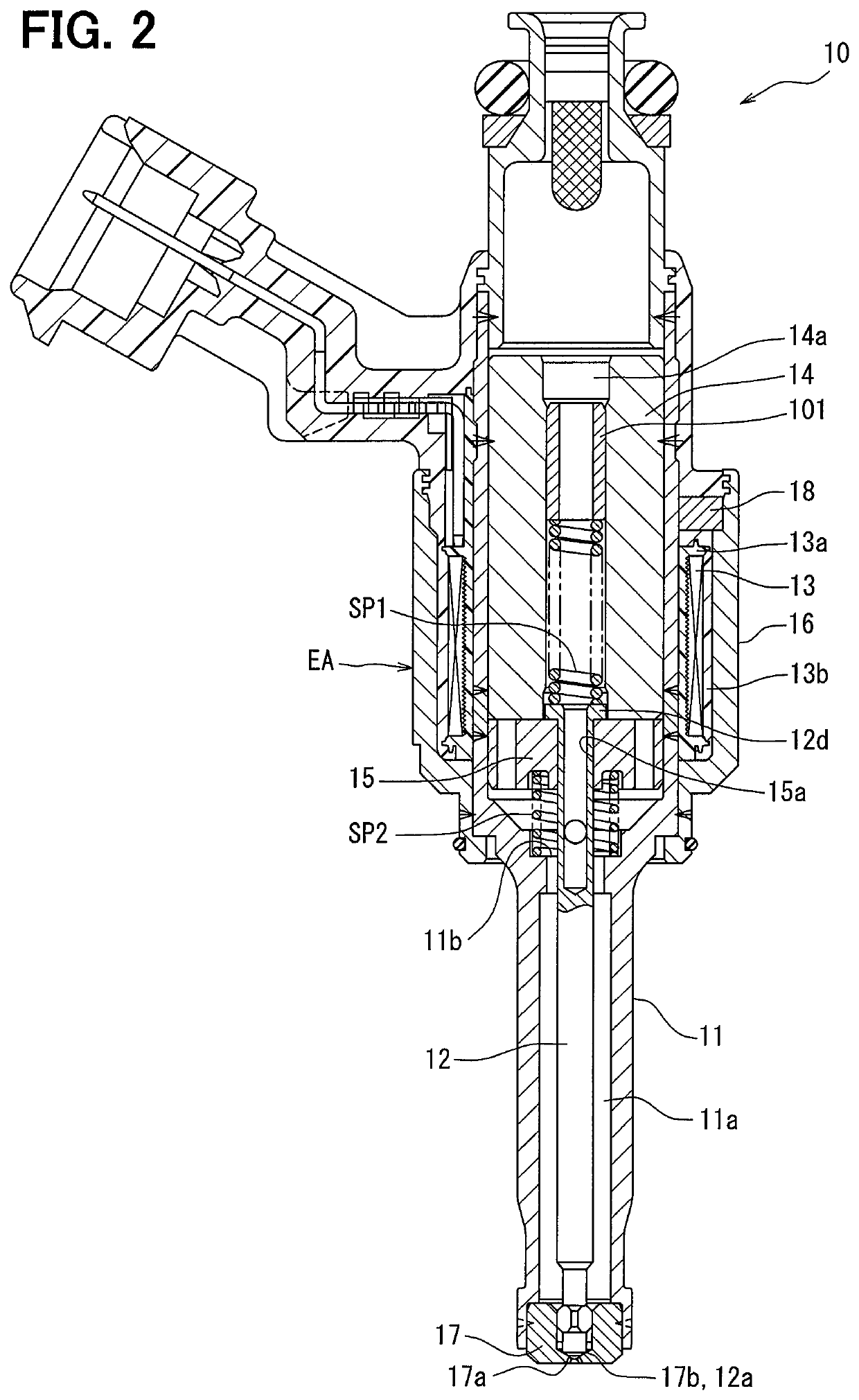
[0024]A first embodiment according to the present disclosure is explained in reference to FIGS. 1 to 10. A fuel injection system 100 shown in FIG. 1 includes a plurality of fuel injection valves 10 and a fuel injection control device 20. The fuel injection control device 20 controls the opening and closing of the fuel injection valves 10 and controls fuel injection into a combustion chamber 2 of an internal combustion engine E. The fuel injection valves 10: are installed in an internal combustion engine E of an ignition type, for example a gasoline engine; and inject a fuel directly into a plurality of combustion chambers 2 of the internal combustion engine E respectively. A mounting hole 4 penetrating concentrically with an axis C of a cylinder is formed in a cylinder head 3 constituting the combustion chamber 2. A fuel injection valve 10 is inserted into and fixed to the mounting hole 4 so that the tip may be exposed into the combustion chamber 2.

[0025]A fuel supplied to the fuel ...


PUM


Abstract

A fuel injection control device has a conduction time calculation unit, a setting unit, a conduction control unit, a detection unit, an estimation unit, and a changing unit. The conduction time calculation unit calculates a conduction time of an electric actuator corresponding to a requested injection quantity during partial lift injection. The setting unit sets a command conduction time. The conduction control unit energizes an electric actuator on the basis of a command conduction time set by the setting unit. The detection unit detects a physical quantity having a correlation with an actual injection quantity during partial lift injection. The estimation unit estimates an actual injection quantity on the basis of a detection result of the detection unit. The changing unit changes a lower limit time on the basis of a deviation between an estimated actual injection quantity and a requested injection quantity.

Description

CROSS REFERENCE TO RELATED APPLICATION[0001]This application is based on Japanese Patent Application No. 2016-93318 filed on May 6, 2016, the disclosure of which is incorporated herein by reference.TECHNICAL FIELD[0002]The present disclosure relates to a fuel injection control device to control an injection quantity of a fuel injected through a fuel injection valve.BACKGROUND ART[0003]In Patent Literature 1, a fuel injection valve to inject a fuel by operating a valve body for valve opening with an electric actuator is disclosed. Further, a fuel injection control device to control a valve opening time of a valve body by controlling a time for energizing an electric actuator and thus control an injection quantity injected per one time valve opening of the valve body is disclosed. A conduction time is set at a time corresponding to an injection quantity that is requested (requested injection quantity).PRIOR ART LITERATURESPatent Literature[0004]Patent Literature 1: JP2015-96720ASUMMAR...

Claims


Application Information

Patent Timeline
Patent Type & Authority Patents(United States)
IPC IPC(8): F02D41/04F02D41/24F02D41/20F02M47/02F02M59/46F02M59/36F02M57/02F02M65/00
CPCF02M59/466F02M47/027F02M57/02F02D41/04F02D41/247F02D41/20F02M59/366F02D2200/0614F02D2041/2055F02M65/00
Inventor SATAKE, NOBUYUKINAKANO, TOMOHIRO
Owner TOYOTA JIDOSHA KK
Learn More