
Electronic control unit of steering system for vehicle

a steering system and electronic control technology, applied in electrical steering, association with control/drive circuits, transportation and packaging, etc., can solve the problems of increasing and increasing the weight of the entire vehicle, so as to reduce the number of necessary parts and facilitate assembly

Active Publication Date: 2020-08-04
HL MANDO CORP
View PDF19 Cites 0 Cited by
  • Summary
  • Abstract
  • Description
  • Claims
  • Application Information

AI Technical Summary

Benefits of technology

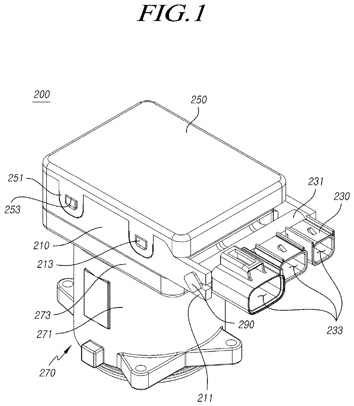
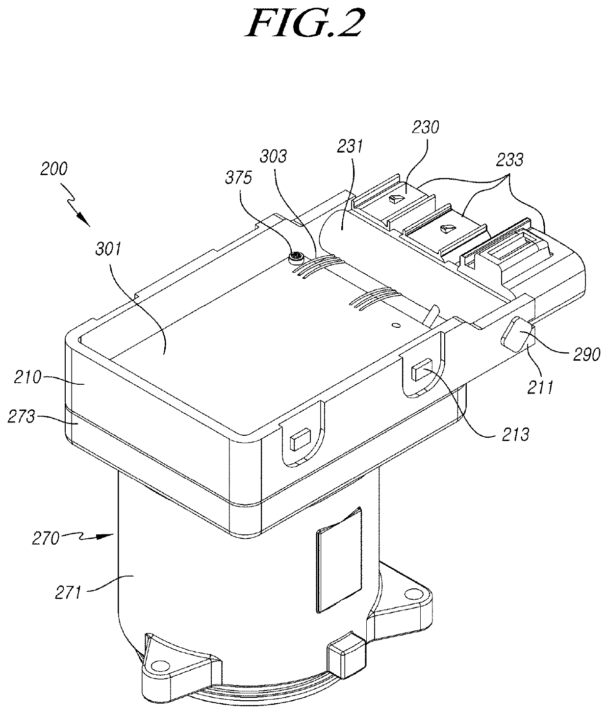
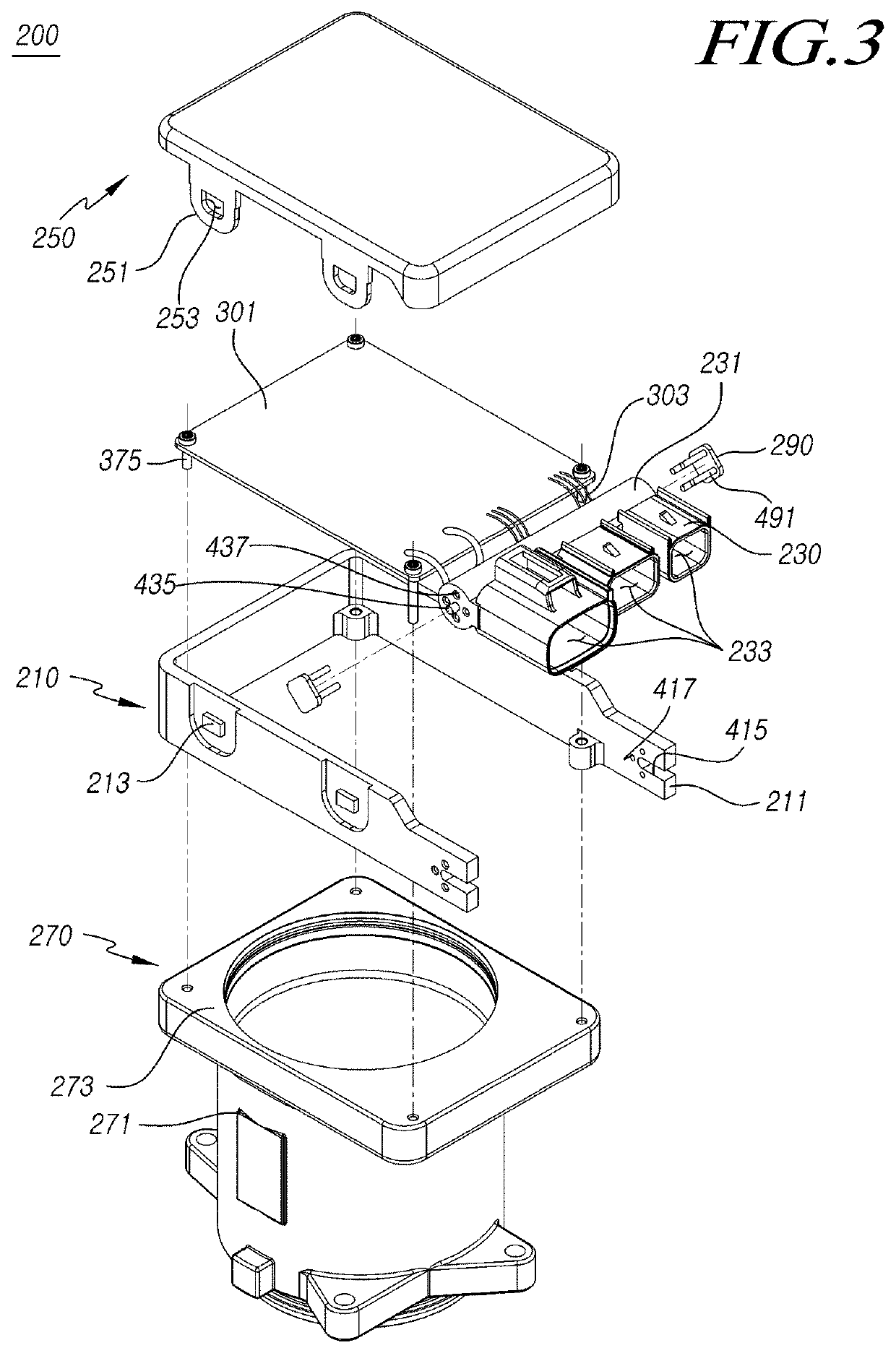
The present disclosure relates to an electronic control unit of a steering system for vehicles. The invention has the following technical effects: 1) The electronic control unit is directly coupled to the outer side of an electric device, eliminating the need for a separate bracket, reducing the number of parts required and making the overall product more compact. 2) The design eliminates the need for a lead wire to change the limited direction of connecting ports in a connector, making assembly easier and securing assembly space without interfering with surrounding parts.

Problems solved by technology

However, according to the electronic control unit of a steering system for a vehicle in the related art, there is a need for a specific bracket structure for fixing the electronic control unit and a long wire harness for connecting the electronic control unit and a motor to each other, so there is a problem that the assembly structure is complicated and the entire weight is increased.
Further, there is also a problem that electromagnetic waves are generated by the long wireless harness.
Further, since the connector of the electronic control unit is integrally formed, the direction of the connecting port, to which the harness is connected, of the connector cannot be changed, so assemblage is difficult.
Further, since the connector is integrally formed, interference with surrounding parts is generated and it is difficult to mount the electronic control unit in a small assembly space.

Method used


Image

  • Electronic control unit of steering system for vehicle
  • Electronic control unit of steering system for vehicle
  • Electronic control unit of steering system for vehicle

Examples


Embodiment Construction

[0023]Hereinafter, embodiments of the present disclosure will be described in detail with reference to the accompanying drawings. In adding reference numerals to elements in each drawing, it should be noted that the same elements are designated by the same reference numerals, if possible, although they are shown in different drawings. Further, in the following description of the present disclosure, a detailed description of known functions and configurations incorporated herein will be omitted when it may make the subject matter of the present disclosure rather unclear.

[0024]In addition, terms, such as first, second, A, B, (a), (b) or the like may be used herein when describing components of the present disclosure. These terms are merely used to distinguish one structural element from other structural elements, and a property, an order, a sequence and the like of a corresponding structural element are not limited by the term. It should be noted that if it is described in the specifi...


PUM


Abstract

The present disclosure relates to an electronic control unit of a steering system for a vehicle. The electronic control unit includes: a case having shaft supporting portions formed at ends of sides facing each other; a connector electrically connected with a substrate and coupled to the case through a rotary shaft coupled to ends of the shaft supporting portions such that that direction of connecting ports to be connected with a harness is adjusted, in which a protrusive first coupling portion is formed at any one of the shaft supporting portion and the rotary shaft and a second recessed coupling portion that is coupled to the first coupling portion is formed at the other one so that the connector is coupled and fixed to the case.

Description

CROSS REFERENCE TO RELATED APPLICATION[0001]This application claims priority from Korean Patent Application No. 10-2017-0020390, filed on Feb. 15, 2017, which is hereby incorporated by reference for all purposes as if fully set forth herein.BACKGROUND OF THE INVENTION1. Field of the Invention[0002]The present disclosure relates to an electronic control unit of a steering system for a vehicle. More particularly, the present disclosure relates to an electronic control unit of a steering system for a vehicle, wherein the electronic control unit is coupled to a flange portion on the outer side of an electric device so there is no need for a specific bracket used for fixing an electronic control unit in the related art, the number of necessary parts can be reduced, the entire product can be compactly configured, there is no need for a lead wire used for changing the limited direction of connecting ports of a connector in the related art, the electronic control unit can be easily assemble...

Claims


Application Information

Patent Timeline
Patent Type & Authority Patents(United States)
IPC IPC(8): B62D5/04H02K11/33H02K5/22B62D15/02
CPCB62D15/0235H02K5/225B62D5/046B62D5/0406B62D5/0409B62D5/0481H02K11/33H02K2213/09B60R16/0231
Inventor KIM, JINHWANJUNG, JOON HOKIM, JI HWAN
Owner HL MANDO CORP
Learn More