
Method and apparatus for determining optimal endotracheal tube size

a technology of endotracheal tubes and tracheal tubes, which is applied in the field of endotracheal tubes, can solve the problems of increasing the risk of vocal cord injury and paralysis, increasing the risk of unplanned extubation, and increasing the risk of endobronchial mal-positioning and associated complications, and achieves the effect of facilitating insertion

Active Publication Date: 2020-07-28
SECURISYN MEDICAL
View PDF30 Cites 1 Cited by
  • Summary
  • Abstract
  • Description
  • Claims
  • Application Information

AI Technical Summary

Problems solved by technology

Research shows that if the machine end of the endotracheal tube cuff (balloon) encroaches on this region, increased risk arises for recurrent laryngeal nerve impingement or pressure directly applied to the vocal cords, either of which may lead to an increased risk for vocal cord injury and paralysis.
Encroachment on this region also leads to an increased risk for unplanned extubation.
It is 2.0 cm long and if the tip of the tube encroaches on this region, an increased risk for endobronchial mal-positioning and associated complications arises.
If an endotracheal tube having too large a diameter (relative to the patient's glottic aperture) is placed through the glottic aperture, the force applied to the vocal cords may cause a subluxation or dislocation of the crico-arytenoid joints leading to vocal cord dysfunction.
Too small a diameter tube may lead to air leaks and inadequate ventilation of the patient.
All of these conditions place the patient at risk for a number of complications arising from tube mal-positioning including pulmonary atelectasis, hypoxemia, pneumonia, pneumothorax, vocal cord injury, vocal cord paralysis, brain injury and death.
No generally accepted and widely utilized method, formula, or system exists that maximizes the probability of choosing the optimally-sized endotracheal tube for adults.
However, even the weight and length-based systems that are considered the gold standard methods for choosing pediatric size tubes use indirect measures (weight / length) that do not correlate highly to nor predict well the tracheal length and glottic opening diameter and, thus, are not great predictors of optimal tube size.
However, even if the clinician chooses a tube having the correct diameter tube, the T-BME length may still be too long, despite ISO standards.
Although ISO standards permit depth localizer markers on endotracheal tubes to provide assistance in positioning the tracheal tube within the trachea, no specific standards exist for the placement of these bands on the tube body.
Moreover, no standards exist for determining VC-T distances for different size (I.D.) tubes.
If any of the T-BME complex is too deep, the patient is at increased risk for endobronchial intubation and any of its inherent complications including hypoventilation, hypoxemia, pneumonia, and pneumothorax.
If the T-BME complex is too shallow, the patient is at increased risk for the inflatable balloon impinging on the recurrent laryngeal nerve and / or vocal cords and the inherent complications of vocal cord paralysis.
In addition, if the T-BME complex is too shallow, the patient is at increased risk for unplanned extubation and its inherent potentially deadly complications including vocal cord injury / paralysis, aspiration pneumonia, hypoxemia, brain injury and death.
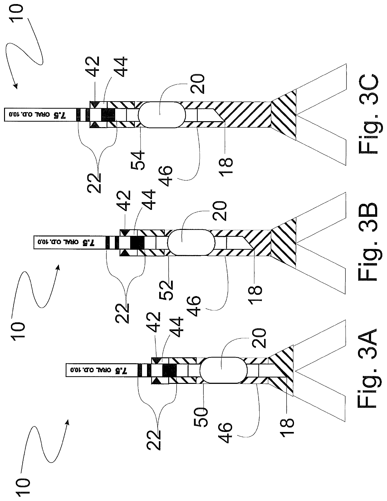
However, it is outside the Safe Positioning Zone 46 and at risk for endobronchial mal-positioning in (a) the short trachea (10 cm).
As shown in FIG. 4, when a 7.5 mm ETT is positioned in a patient with a short 10 cm trachea based upon the manufacturer depth localizer band properly placed at the vocal cords, the tip of the tube is noted to be too deep and is well within the Lower Trachea—Unsafe Positioning Zone, putting the patient at increased risk for endobronchial mal-positioning.
If once the tip is noted to be too deep and the ETT is withdrawn several centimeters so that the tip of the tube is within the Safe Positioning Zone 46, then the machine end of the balloon encroaches on the Upper Trachea—Unsafe Positioning Zone, putting the patient at increased risk for impingement of the vocal cords and laryngeal nerve and increased risk for unplanned extubation.
Therefore, a 7.5 mm ETT, manufactured under current diameter driven specifications, cannot be properly placed in any patient with a short trachea (10 cm) without putting the patient at increased risk for complications.

Method used


Image

  • Method and apparatus for determining optimal endotracheal tube size
  • Method and apparatus for determining optimal endotracheal tube size
  • Method and apparatus for determining optimal endotracheal tube size

Examples


Embodiment Construction

[0053]Selected embodiments of the present invention will now be explained with reference to the drawings. It will be apparent to those skilled in the art from this disclosure that the following descriptions of the embodiments of the present invention are provided for illustration only and not for the purpose of limiting the invention as defined by the appended claims and their equivalents.

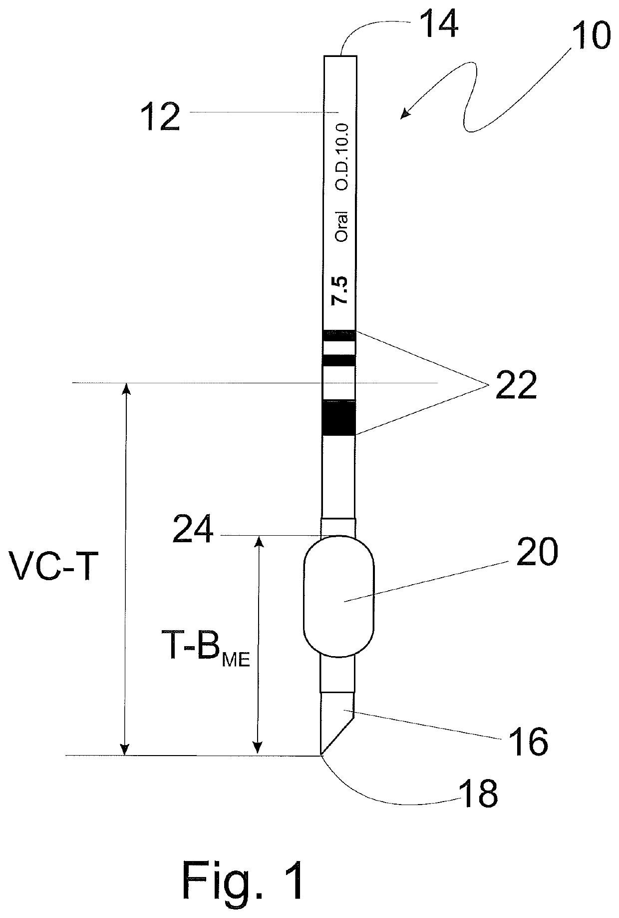
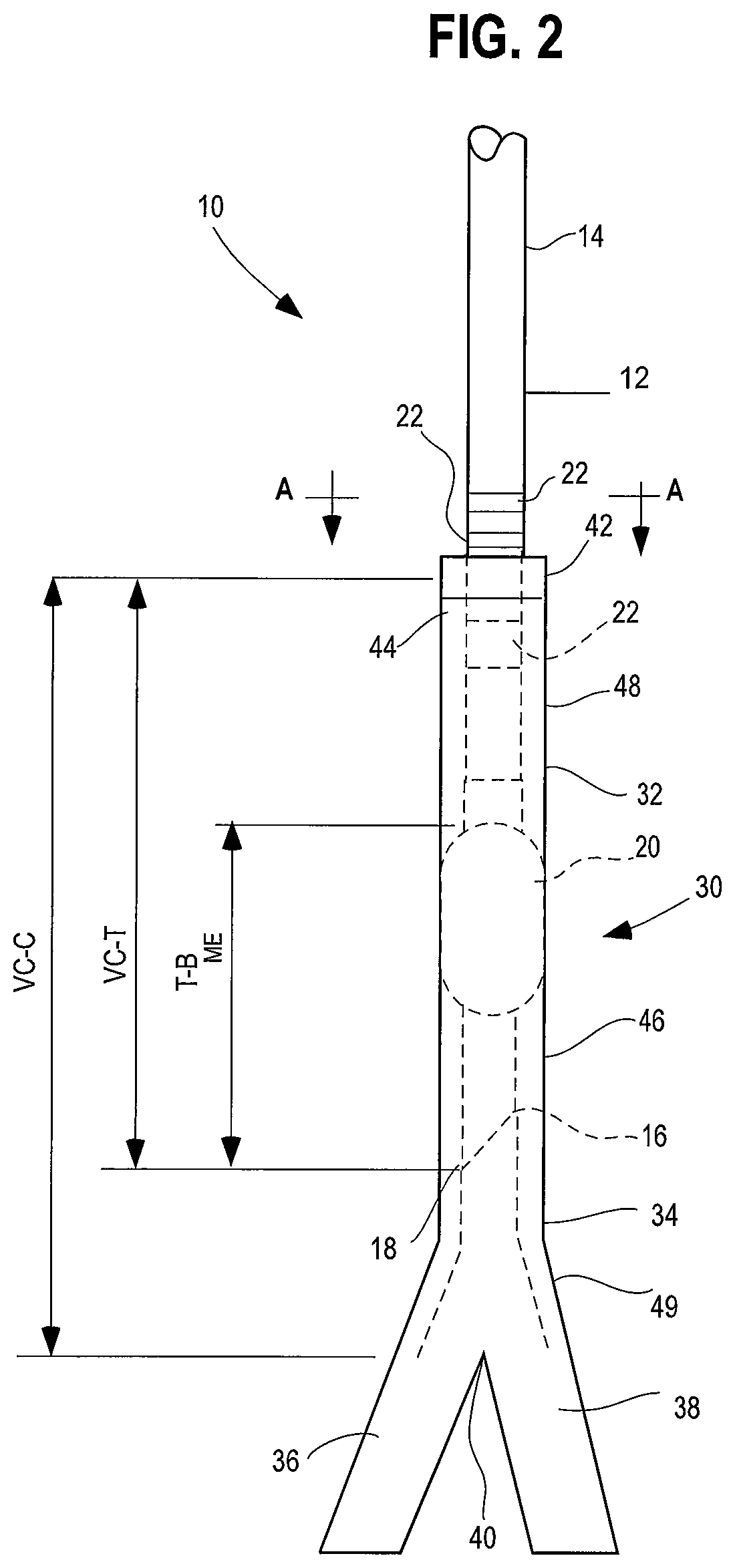
[0054]Referring now to FIG. 1, an endotracheal tube (ETT) of typical construction is shown at 10. The ETT includes a tubular body 12 having a proximal or machine end 14 and a distal or patient end 16. The distal end 16 includes a beveled tip 18 defined by the most distal part of the bevel to facilitate insertion into a patient's trachea (not shown). The ETT also includes an inflatable endotracheal tube cuff or balloon 20 to provide a seal between the ETT and the trachea after the tube is placed in the trachea, as is known in the art. The cuff or balloon may be adjustably inflated to a preselected p...


PUM


Abstract

A method and apparatus for determining the optimal endotracheal tube size for the intubation of a patient based upon both optimal tube length and optimal tube diameter which are determined by using either direct or indirect measurement devices or techniques to measure the patient's glottis aperture and tracheal length. The apparatus may include a maneuverable arm, a fiber optic video guidance system and an introducer guide to maneuver an end of the apparatus around obstructions in a patient who has a difficult airway to facilitate insertion of either an optimally sized endotracheal tube or a standard endotracheal tube into the patient's airway.

Description

CROSS-REFERENCE TO RELATED APPLICATIONS[0001]This application claims priority to U.S. Provisional Patent Application No. 62 / 000,182 filed May 19, 2014, the entire disclosure of which is incorporated herein by reference.FIELD OF THE INVENTION[0002]The present invention generally relates to endotracheal tubes. More specifically, the present invention relates to a method and apparatus for more accurately determining the optimal endotracheal tube size for safe and effective intubation and airway maintenance of any individual patient requiring placement of an endotracheal tube.BACKGROUND OF THE INVENTION[0003]When a patient is unable to breathe on his or her own due to a critical illness or injury, it becomes necessary for a clinician to place an endotracheal tube (also referred to herein as “ETT”) into that patient's trachea to facilitate the patient's breathing. Similarly, when a patient is unable to breathe independently because s / he is under general anesthesia for surgery, it becomes...

Claims


Application Information

Patent Timeline
Patent Type & Authority Patents(United States)
IPC IPC(8): A61M16/04A61B8/12A61B1/00A61B5/107A61B1/267A61B5/00A61B5/0205A61B5/08
CPCA61B8/12A61B1/00165A61B5/6867A61B5/08A61M16/0434A61M16/0488A61B5/0205A61B5/1076A61B1/267A61B5/0084A61M2205/583
Inventor KANOWITZ, ARTHUR
Owner SECURISYN MEDICAL
Learn More