
Optical displacement detector with adjustable pattern direction

a technology of optical displacement detector and pattern direction, which is applied in the direction of wing accessories, instruments, and reradiation, etc., can solve the problems of labor-intensive and inefficient, false or incorrect measurements, and difficult installation of existing optical detector systems, and achieve the effect of adding to installation cost and complexity

Active Publication Date: 2020-07-21
TYCO FIRE & SECURITY GMBH
View PDF25 Cites 0 Cited by
  • Summary
  • Abstract
  • Description
  • Claims
  • Application Information

AI Technical Summary

Benefits of technology

The proposed detector system has three main technical effects: adjustable optical axis, sensor assembly fixing system, and ease of installation. The detector system has an adjustable optical axis, meaning the installed detectors can adjust how the light beams impinge upon objects by adjusting the optical axis. This makes it easier for installers to properly detect displacement of objects without having to re-mount the detectors. Additionally, the sensor assembly fixing system prevents rotation of the sensor assembly in the mounting bracket, resulting in more accurate measurements. These features make the detector system easier to install and use, while also improving accuracy and efficiency.

Problems solved by technology

Installation of existing optical detector systems can be challenging for several reasons.
This is labor-intensive and inefficient.
Second, the light sensors of these systems are susceptible to parasitic reflection from neighboring objects, which can create false or incorrect measurements.
As a result, installers must also position these optical detector systems during installation to avoid stray light, which also adds to installation cost and complexity.

Method used


Image

  • Optical displacement detector with adjustable pattern direction
  • Optical displacement detector with adjustable pattern direction
  • Optical displacement detector with adjustable pattern direction

Examples


Embodiment Construction

[0031]The invention now will be described more fully hereinafter with reference to the accompanying drawings, in which illustrative embodiments of the invention are shown. This invention may, however, be embodied in many different forms and should not be construed as limited to the embodiments set forth herein; rather, these embodiments are provided so that this disclosure will be thorough and complete, and will fully convey the scope of the invention to those skilled in the art.

[0032]As used herein, the term “and / or” includes any and all combinations of one or more of the associated listed items. Further, the singular forms and the articles “a”, “an” and “the” are intended to include the plural forms as well, unless expressly stated otherwise. It will be further understood that the terms: includes, comprises, including and / or comprising, when used in this specification, specify the presence of stated features, integers, steps, operations, elements, and / or components, but do not pre...


PUM


Abstract

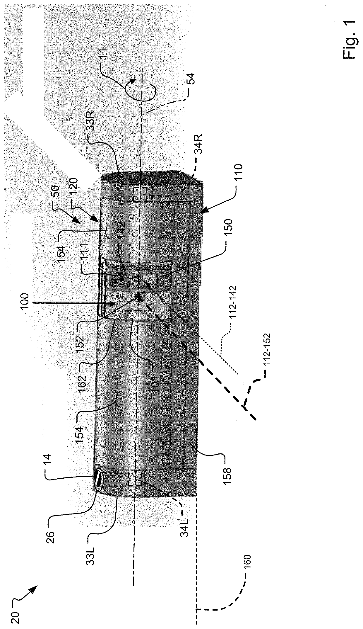
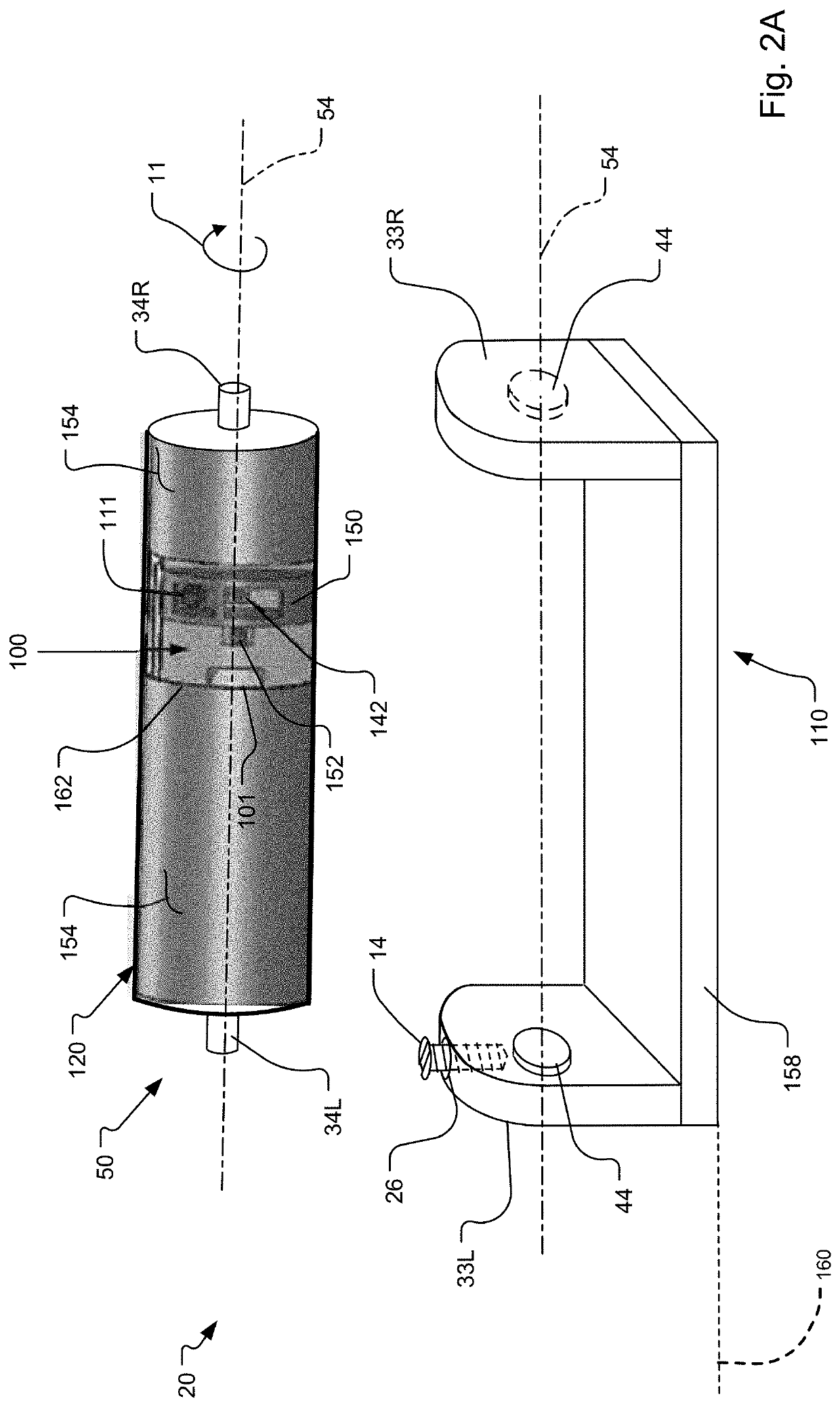
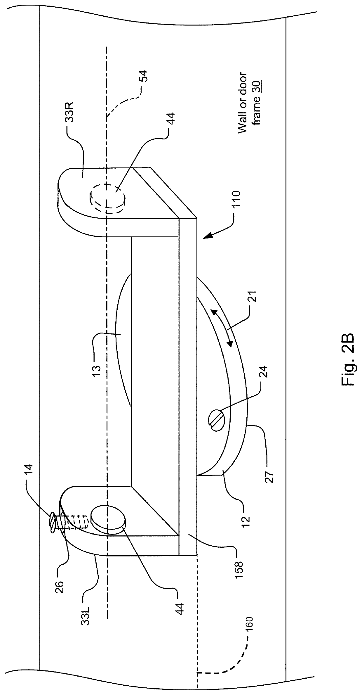
A system and method for an optical displacement detector system with adjustable pattern direction are disclosed. In an embodiment, the detector system includes a mounting bracket and a sensor assembly. The sensor assembly includes a housing, and a sensor module in the housing. The sensor assembly can be rotated with respect to the mounting bracket to adjust an optical axis of the sensor module. In another embodiment, the detector system includes a turntable that enables additional adjustment of the optical axis. Such a system significantly improves installation of these detector systems as compared to existing optical displacement detector systems, which have fixed optical axes. In one application, the detector system is installed in a door system having a door and door frame, and detects displacement of the door.

Description

BACKGROUND OF THE INVENTION[0001]Displacement detector systems are commonly used in many intrusion systems, and in security systems more generally. Most often, these detector systems are used to detect whether doors or windows are ajar or secured. A typical application for these detector systems is a door system that includes a door frame and a door. More generally, however, these detector systems can be used in other applications that require proximity and / or end position sensing, distance measurements such as nano-distance measurements, or moving part position sensing.[0002]In these intrusion / security systems, the displacement sensor systems are typically monitored by a system control panel via a network. In this way, the control panel can monitor whether doors or windows are ajar or secured, for example.[0003]Displacement detector systems are often constructed as two major pieces that work together as a pair. The two pieces are separated by a distance when installed. In these two...

Claims


Application Information

Patent Timeline
Patent Type & Authority Patents(United States)
IPC IPC(8): G01D5/32E05F15/43G01D11/24G08B13/08G01S7/481G08B13/181G08B29/22
CPCG01D11/245G08B13/08G01S7/4813G01D5/32E05F15/43E05F2015/434G08B13/181G08B29/22G01S17/08
Inventor ZHEVELEV, BORISLITVAK, ELI
Owner TYCO FIRE & SECURITY GMBH
Learn More