Tactile sensation presenting device

a technology of tactile sensation and presenting device, which is applied in the direction of mechanical control devices, instruments, manual control with single controlling member, etc., can solve the problems of insufficient accuracy, insufficient richness of expression, and insufficient fineness of tactile sensation presentation, so as to achieve finer tactile sensation and further efficiently dissipate heat generated by the peltier elemen

Active Publication Date: 2020-06-30
ALPS ALPINE CO LTD
View PDF17 Cites 1 Cited by
  • Summary
  • Abstract
  • Description
  • Claims
  • Application Information

AI Technical Summary

Benefits of technology

[0010]Thereby, because presented information is controlled based on the obtained operation information, a more complex tactile sensation can be presented. Also, because control conditions can be changed according to the state of the operating part, the efficiency and speed of control can be enhanced. As a result, a finer tactile sensation can be presented.
[0023]According to an aspect of the present invention, because it is possible to present vibration information, warm / cold information, and pressure information, it is possible to present a finer tactile sensation.

Problems solved by technology

However, in the tactile sensation transmitting device described in Patent Document 1, although it is possible to present both vibration and warm sensation simultaneously, one set of vibration information and one warm sensation can only be presented.
Therefore, for example, in expressing a texture or a temperature sensation corresponding to an actual article or movement or deformation when applying force to the article, fineness of tactile sensation presentation, richness of expression, and accuracy are insufficient.

Method used


Image

  • Tactile sensation presenting device
  • Tactile sensation presenting device
  • Tactile sensation presenting device

Examples


first embodiment

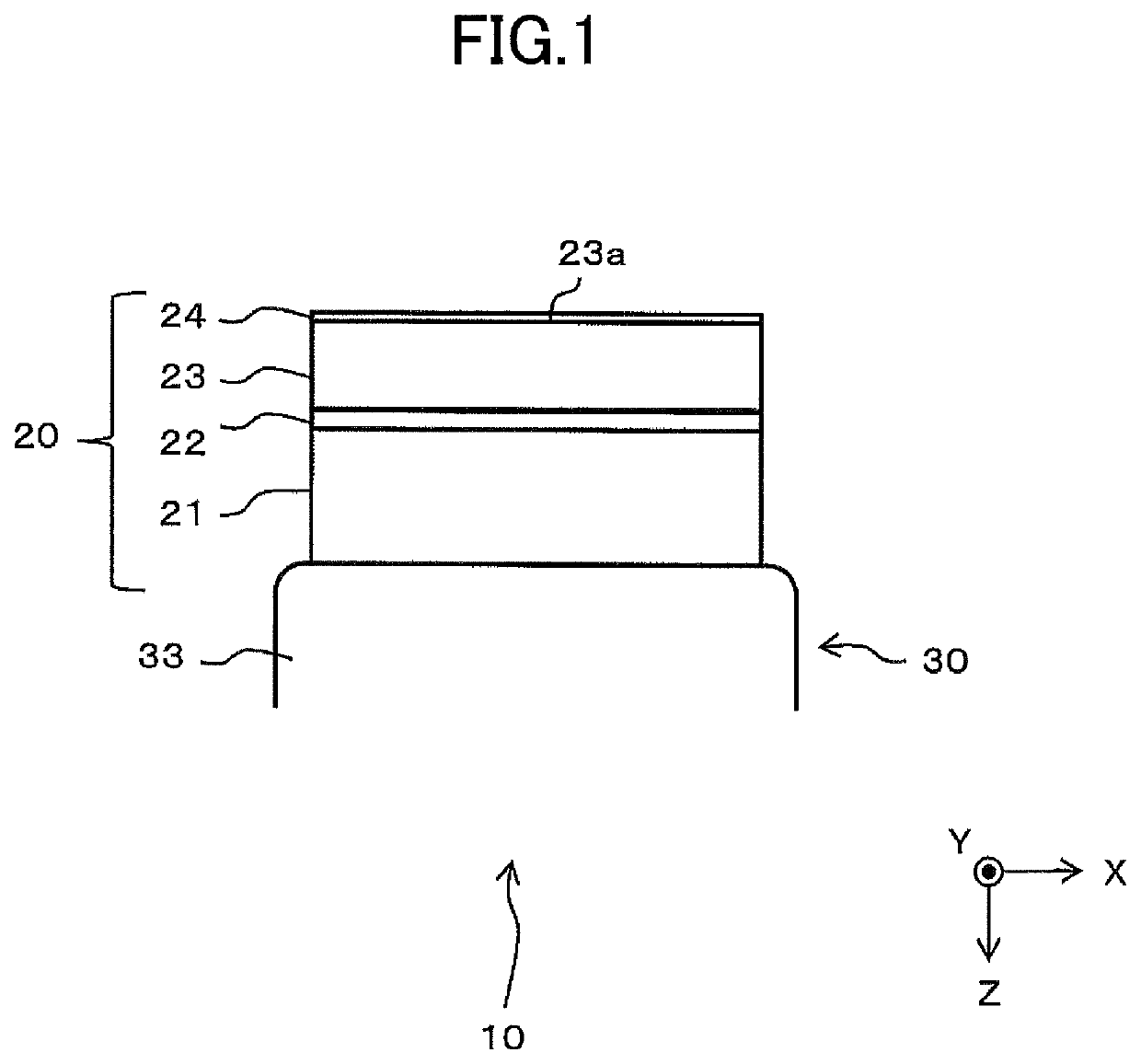
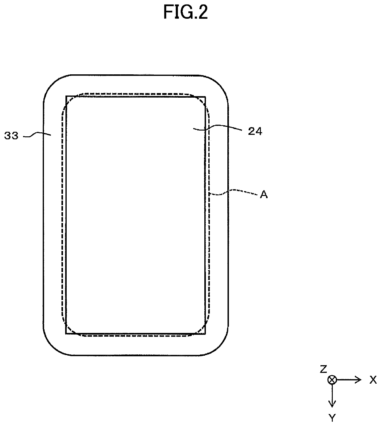
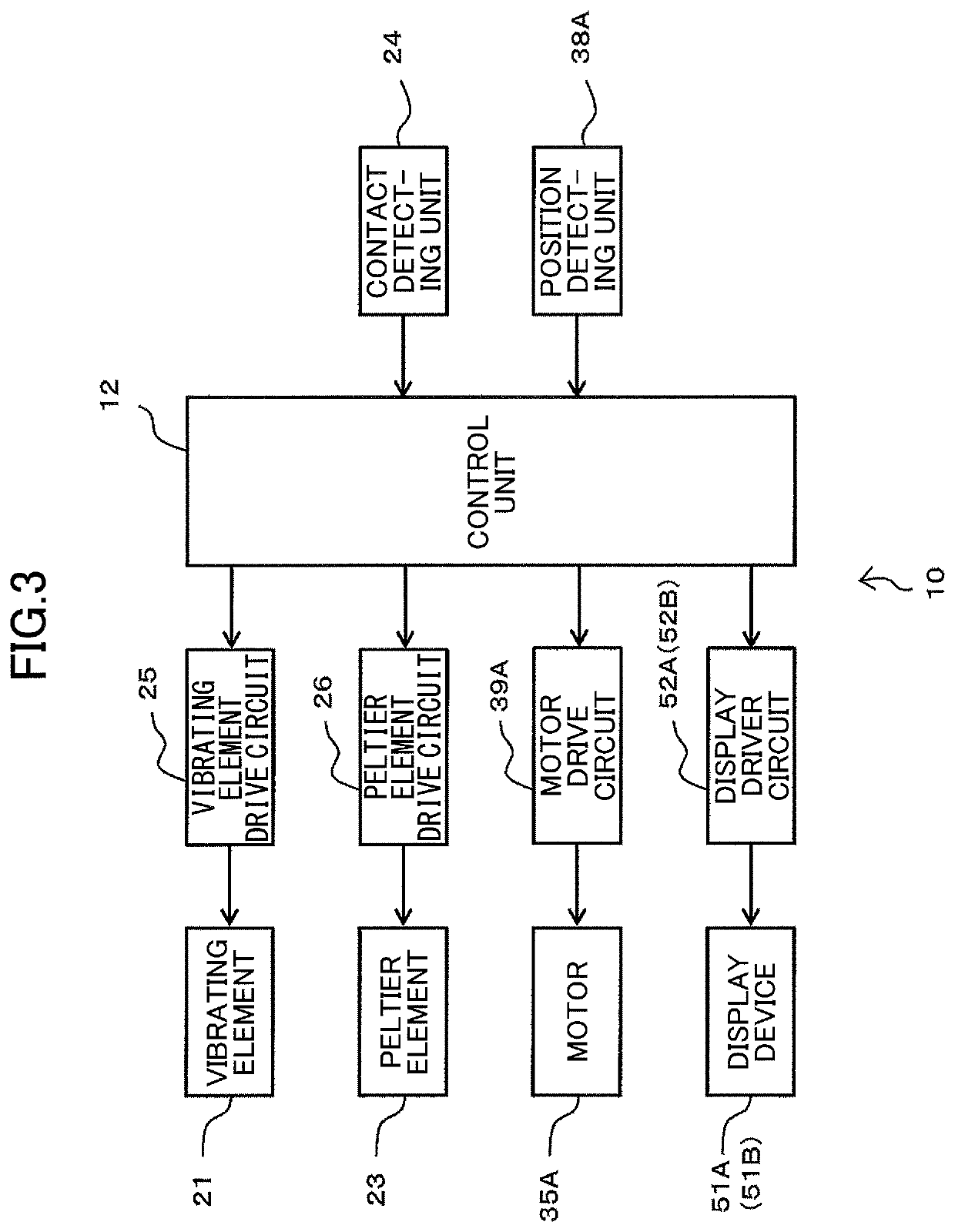
[0037]FIG. 1 is a side view illustrating a schematic configuration of a tactile sensation presenting device 10 according to a first embodiment; FIG. 2 is a plan view of the tactile sensation presenting device 10 that is illustrated in FIG. 1; and FIG. 3 is a functional block diagram of the tactile sensation presenting device 10. In each drawing, X-Y-Z coordinates are illustrated as reference coordinates. In the following description, a state viewed from the upper side to the lower side in the Z direction may be referred to as plan view, and the Z direction is a direction perpendicular to an X-Y plane.

[0038]As illustrated in FIG. 1 and FIG. 2, the tactile sensation presenting device 10 includes a pressure sensation generating unit 30 (pressure sensation generating unit 30A, 30B, 30C in FIG. 6A) and a tactile sensation generating unit 20 is arranged on a support 33 (33A, 33B, 33C in FIG. 6A) of the pressure sensation generating unit 30.

[0039]As illustrated in FIG. 1, a vibrating eleme...

second embodiment

[0098]FIG. 10 is a side view illustrating a schematic configuration of a tactile sensation presenting device 110 according to a second embodiment, and FIG. 11 is a plan view illustrating a schematic configuration of the tactile sensation presenting device 110 according to the second embodiment.

[0099]The tactile sensation presenting device 110 of the second embodiment differs from that of the first embodiment in that a pressure sensation generating unit 130 capable of tilting the tactile sensation generating unit 20 is used instead of the pressure sensation generating unit 30A, 30B, or 30C of the first embodiment. Because the contact area A and the configuration of the tactile sensation generating unit 20 are similar to those in the first embodiment, the same reference numerals are used.

[0100]As illustrated in FIG. 10 or FIG. 11, the pressure sensation generating unit 130 includes a fixed member 131, five pin-shaped air cylinders 132A, 132B, 132C, 132D, and 132E disposed on the fixed...


PUM


Abstract

A tactile sensation presenting device includes: a pressure sensation generating unit configured to present pressure information; and a tactile sensation generating unit arranged on the pressure sensation generating unit. The tactile sensation generating unit includes a vibrating element configured to present vibration information; a warmth / coldness presenting element provided above the vibrating element and configured to present warm / cold information. The vibration information, the warm / cold information, and the pressure information are presented to an operating part in contact with a tactile sensation presentation surface of the tactile sensation generating unit.

Description

CROSS-REFERENCE TO RELATED APPLICATIONS[0001]This application is a continuation of International Application No. PCT / JP2018 / 001987, filed on Jan. 23, 2018 and designated the U.S., which claims priority to Japanese Patent Application 2017-019193, filed on Feb. 6, 2017. The contents of these applications are incorporated herein by reference in their entirety.BACKGROUND OF THE INVENTION1. Field of the Invention[0002]The present invention relates to a tactile sensation presenting device for presenting warm / cold information and vibration information when touched by an operating part such as a finger.2. Description of the Related Art[0003]Patent Document 1 describes a device in which a tactile sensation presenting device that generates vibration by a voice coil, a piezoelectric element, or the like, a Peltier element that presents a warm sensation, and a sensor that measures a temperature of skin are disposed on a base. The tactile sensation presenting device and the sensor are directly d...

Claims


Application Information

Patent Timeline
Patent Type & Authority Patents(United States)
IPC IPC(8): G06F3/01G06F3/044G05G9/047
CPCG05G9/047G06F3/0444G06F3/016G06F2203/015G06F3/03547H01H13/85H01H2003/008H01H2215/05H01H2215/052H01H2217/024H01H2239/06
Inventor SATO, KUNIOTAKAI, DAISUKEKAWANA, YUZURU
Owner ALPS ALPINE CO LTD
Why Eureka
Try Eureka