System for optimizing the charging of electric vehicles using networked distributed energy storage systems

a technology of energy storage and electric vehicles, applied in the integration of power network operation systems, electrical energy, greenhouse gas reduction, etc., can solve the problems of high energy costs for users, high energy costs for energy storage mediums, and high cost of energy storage mediums, especially battery energy storag

Active Publication Date: 2020-06-23
STEM
View PDF96 Cites 6 Cited by
  • Summary
  • Abstract
  • Description
  • Claims
  • Application Information

AI Technical Summary

Benefits of technology

[0012]Embodiments of the invention may further provide a system for managing power, comprising a first storage device that is in electric communication with an electric power line, wherein the first storage device comprises a first energy source and a first bidirectional power converter that is coupled between the first energy source and the electric power line, a first sensor configured to monitor the fluctuations in the amount of power flowing through the electric power line, a electric vehicle charging station having one or more electrical connections that are coupled to the electric power line, and a first controller that is in communication with the first bidirectional power converter and the first sensor, and is configured to control a transfer of energy between the electric power line and the first energy source through the first bidirectional power converter so that the fluctuations in power flowing through the electric power line can be controlled.

Problems solved by technology

The cost to a utility for generating or purchasing electrical energy increases dramatically during periods of peak use versus periods of off-peak usage.
The higher rates charged during peak usage periods can lead to significantly higher energy costs for the user, especially when the user's period(s) of high demand coincides with or falls within the interval set by the utility as peak hours.
Energy storage mediums, especially battery energy storage, are expensive and, while various techniques are known by which an energy storage system can be used to optimize energy use at a business or home, such techniques are generally inefficient in applying stored energy to effectively control the energy use at an electric load location.
Consequently, an impractical quantity of energy storage mediums are required at an electric load location to realize useful energy arbitrage.
Each of these approaches generally requires an uneconomical amount of energy storage capacity in order to offset demand peaks at the electric load location.
Furthermore, use of a single demand set-point typically results in an energy storage system running out of energy storage availability due to over-reaction of the controlling components to the demand set point set by the controlling system.
Current solutions for these types of electric load locations entail multiple discrete energy storage systems, where if any piece of an energy storage system is damaged, the ability to control the power demand at the entire electric load location is at risk of becoming inoperable due to the system's inability to compensate to the change in power control.
Today's electric grid is typically undersupplied and over demanded at critical points during the day and at other times it is oversupplied and under demanded.
With an increase in unstable renewable generation (e.g., wind and solar) and a decrease in the number of traditional generators, it is becoming more and more difficult for utilities and grid operators to reliably manage their transmission and distribution grids.
Grid managers are not able to control when or where electric vehicles are charged, and the charging load can range from several kilowatts to around 100 kW, depending on the type of charging station and the number of users at the charging station.
Charging electric vehicles can overload transformers and other distribution equipment, causing early failure and higher distribution costs, and add significant unpredictable load to the electric grid.

Method used


Image

  • System for optimizing the charging of electric vehicles using networked distributed energy storage systems
  • System for optimizing the charging of electric vehicles using networked distributed energy storage systems
  • System for optimizing the charging of electric vehicles using networked distributed energy storage systems

Examples


Embodiment Construction

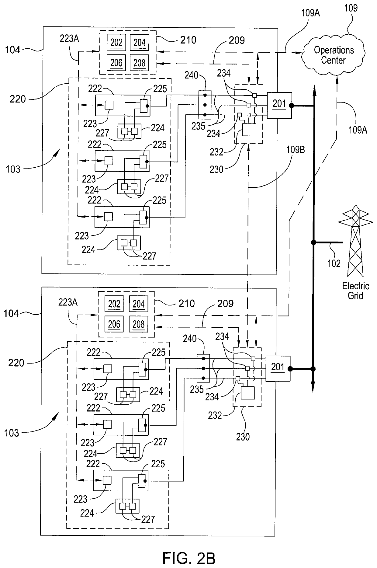
[0045]Embodiments of the present invention include control methods employed in multiphase distributed energy storage systems that are located behind utility meters typically located at, but not limited to, medium and large commercial and industrial locations. Some embodiments of the invention use networked multiphase distributed energy storage systems located at an electric load location 104 or installed at interconnection points along the electric power distribution grid 102 to provide a means for balancing the load created from an electric charging station, which are adapted to transfer power between one or more electric vehicles and the electric power grid 102.

[0046]According to such control methods, these multiphase distributed energy storage systems operate semi-autonomously at the electric load location, but each may be in frequent contact with a cloud-based optimization engine that is configured to develop energy control solutions based on various data inputs and to communica...


PUM


Abstract

Embodiments of the present invention include control methods employed in multiphase distributed energy storage systems that are located behind utility meters typically located at, but not limited to, medium and large commercial and industrial locations. Some embodiments of the invention use networked multiphase distributed energy storage systems located at an electric load location or installed at interconnection points along the electric power distribution grid to provide a means for balancing the load created from an electric charging station, which are adapted to transfer power between one or more electric vehicles and the electric power grid.

Description

CROSS-REFERENCE TO RELATED APPLICATIONS[0001]This application claims the benefit of U.S. Provisional Patent Application Ser. No. 61 / 706,091, filed Sep. 26, 2012 and U.S. Provisional Patent Application Ser. No. 61 / 801,274, filed Mar. 15, 2013, which are all hereby incorporated herein by reference.BACKGROUND OF THE INVENTION[0002]Field of the Invention[0003]Embodiments of the present invention generally relate to a method and an apparatus for controlling fluctuations in power and amount of power used at an electric load location and / or on an electrical grid.[0004]Description of the Related Art[0005]Energy demand at a commercial site, such as a business, or at home will vary over the time of day. In a typical home or hotel setting, there is a peak in the morning when the occupants get up and when the occupants return home at the end of the day. This typically creates two demand peaks during a normal day. Commercial buildings tend to follow different patterns depending on the nature of ...

Claims


Application Information

Patent Timeline
Patent Type & Authority Patents(United States)
IPC IPC(8): H02J3/14H02J13/00H02J3/32H02J3/38
CPCH02J3/14H02J3/00H02J3/32H02J3/38Y02E60/721Y02P80/11Y02E70/30Y02B90/222Y02E40/72Y04S20/12Y04S10/123Y04S10/126H02J7/00712H02J2300/20H02J3/381H02J13/00034Y02B90/20Y02E60/00Y02P80/10Y04S20/222Y02B70/3225H02J13/00022H02J3/322H02J13/00002H02J2300/22Y04S40/126Y02E40/70
Inventor KEARNS, BENHYDE, III, HENRY HOLBROOKBURLINSON, JONSTEVENS, DREW
Owner STEM
Why Eureka
Try Eureka