Dielectric working fluid centralized management system

a working fluid and centralized management technology, applied in the direction of metal-working equipment, manufacturing tools, electrical-based machining equipment, etc., can solve the problems of inefficiency and increased cost of electrical discharge machines, and achieve the effect of quick maintenance operations, easy adjustment and management, and improved productivity

Active Publication Date: 2020-06-23
FANUC LTD
View PDF19 Cites 0 Cited by
  • Summary
  • Abstract
  • Description
  • Claims
  • Application Information

AI Technical Summary

Benefits of technology

[0009]Thus, the present invention has the object of providing a dielectric working fluid centralized management system, which facilitates maintenance and inspection, and further lowers the cost of devices or components that serve to adjust the fluid quality of a dielectric working fluid in a plurality of wire electrical discharge machines.
[0021]According to the present invention, the fluid quality of the dielectric working fluid of each of the plurality of wire electrical discharge machines can be managed collectively. Further, maintenance and inspection of devices or materials that adjust the fluid quality of the dielectric working fluid of the plurality of wire electrical discharge machines is facilitated, and together therewith, since there is no need to provide the dielectric working fluid adjustment apparatus in each of the wire electrical discharge machines, equipment expenditures can be reduced in cost.

Problems solved by technology

Further, in the case that the fluid quality of the dielectric working fluid of each of the electrical discharge machines is managed, while using consumables such as filters, etc., and temperature regulators that are provided in each of the electrical discharge machines, the cost for the electrical discharge machines tends to increase together with the occurrence of inefficiencies.

Method used


Image

  • Dielectric working fluid centralized management system
  • Dielectric working fluid centralized management system
  • Dielectric working fluid centralized management system

Examples


Embodiment Construction

[0026]A preferred embodiment of a dielectric working fluid centralized management system according to the present invention shall be presented and described in detail below with reference to the accompanying drawings.

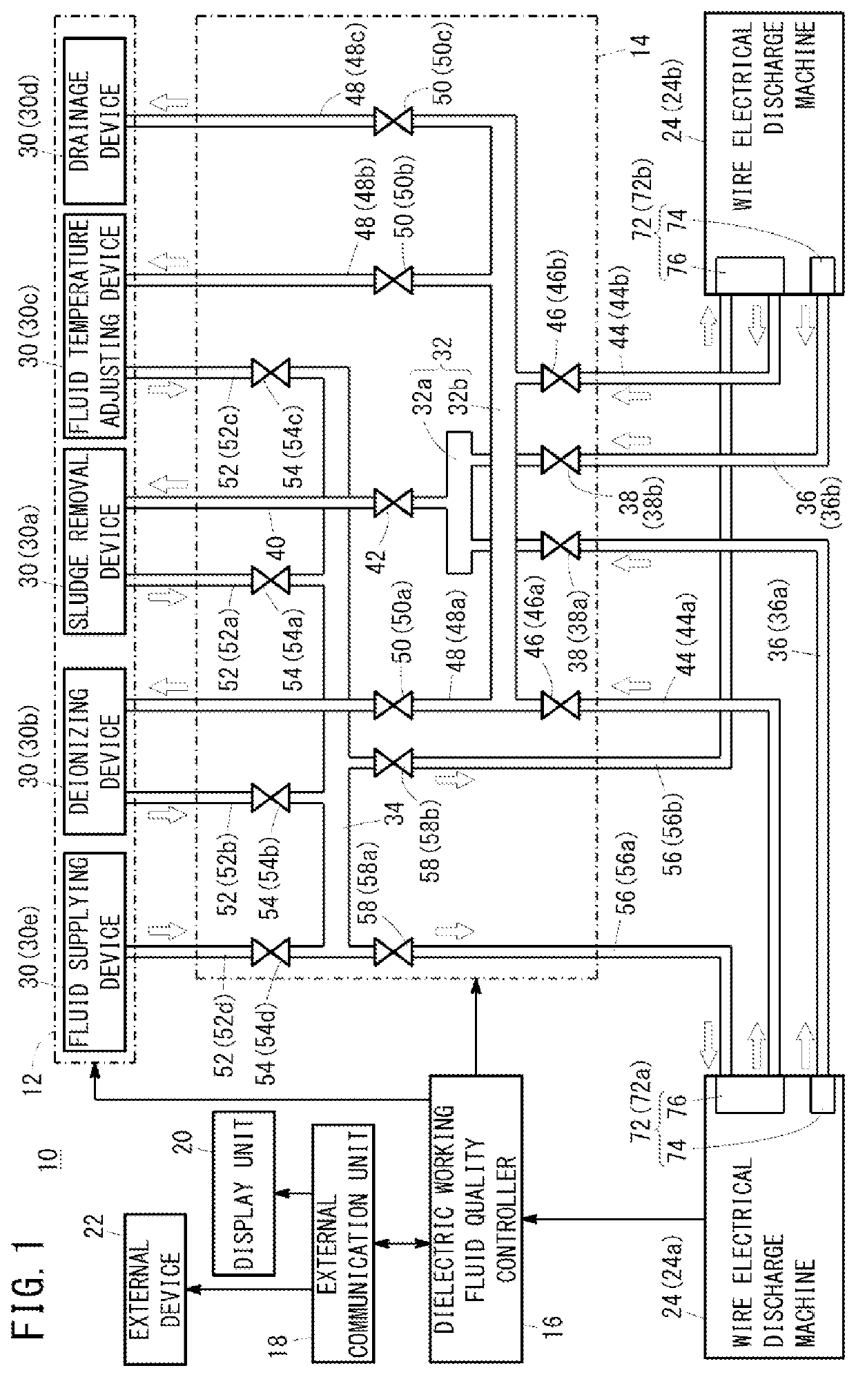
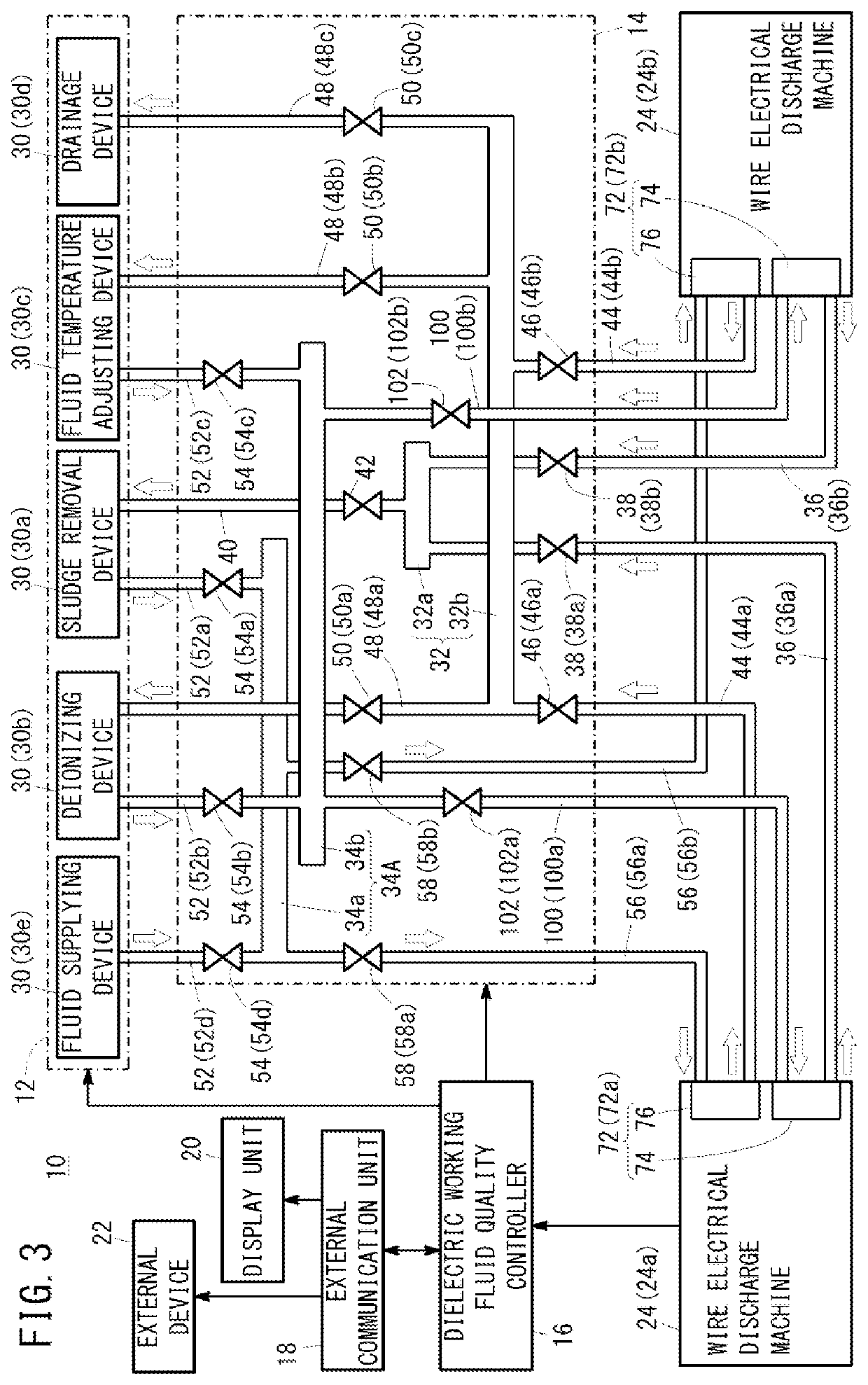
[0027]FIG. 1 is a view showing a configuration of a dielectric working fluid centralized management system 10 according to a present embodiment. The dielectric working fluid centralized management system 10 is equipped with a dielectric working fluid adjustment apparatus 12, a dielectric working fluid delivery and reception control member 14, a dielectric working fluid quality controller 16, an external communication unit 18, a display unit 20, and an external device 22. In the dielectric working fluid centralized management system 10, batch management can be performed for the fluid quality of the dielectric working fluid LQ of each of a plurality of wire electrical discharge machines 24, i.e., the fluid quality can be managed collectively.

[0028]In order to facilitate u...


PUM

PropertyMeasurementUnit
electrical conductivityaaaaaaaaaa
temperatureaaaaaaaaaa
timeaaaaaaaaaa

Abstract

A dielectric working fluid centralized management system is equipped with a dielectric working fluid adjustment apparatus for adjusting the fluid quality of a dielectric working fluid of a plurality of wire electrical discharge machines, a dielectric working fluid delivery and reception control member for controlling delivery and reception of the dielectric working fluid between a plurality of dielectric working fluid storage tanks disposed corresponding respectively to the plurality of wire electrical discharge machines, and in which the dielectric working fluid is stored, and the dielectric working fluid adjustment apparatus, and a dielectric working fluid quality controller, which receives dielectric working fluid information from the plurality of wire electrical discharge machines and controls the dielectric working fluid delivery and reception control member, or both the dielectric working fluid delivery and reception control member and the dielectric working fluid adjustment apparatus.

Description

CROSS-REFERENCE TO RELATED APPLICATION[0001]This application is based upon and claims the benefit of priority from Japanese Patent Application No. 2016-032673 filed on Feb. 24, 2016, the contents of which are incorporated herein by reference.BACKGROUND OF THE INVENTION[0002]Field of the Invention[0003]The present invention relates to a dielectric working fluid centralized management system for adjusting and managing the fluid quality of a dielectric working fluid in a plurality of wire electrical discharge machines.[0004]Description of the Related Art[0005]A wire electrical discharge machine is a processing machine for performing machining on a workpiece by way of electrical discharge that occurs between a wire electrode and the workpiece through a dielectric working fluid. At this time, because the dielectric working fluid becomes contaminated by machining waste (hereinafter referred to as sludge) that is generated during machining, there is a need to treat the polluted fluid (poll...

Claims


Application Information

Patent Timeline
Patent Type & Authority Patents(United States)
IPC IPC(8): B23H1/10B23H7/36B23H7/02
CPCB23H7/36B23H1/10B23H7/02B23H11/00
Inventor FURUTA, TOMOYUKI
Owner FANUC LTD
Why Eureka
Try Eureka