
Method for operating a textile machine, and textile machine for producing roving

a textile machine and textile machine technology, applied in the direction of continuous wounding machines, textiles and papermaking, thin material processing, etc., can solve the problem and achieve the effect of not being able to produce more roving

Active Publication Date: 2020-06-16
MASCHINENFABRIK RIETER AG
View PDF19 Cites 0 Cited by
  • Summary
  • Abstract
  • Description
  • Claims
  • Application Information

AI Technical Summary

Benefits of technology

The patent describes a method for restarting a textile machine that has experienced an interruption in normal operation. The method involves stopping the drafting system and consolidating means to prevent further fiber bundling, cleaning the consolidating means, and monitoring the roving produced during normal operation for physical characteristics. The method also includes restarting the machine and re-establishing the flow of roving between the consolidating means and winding device or tube. The technical effects of this patent include improved machine productivity, reduced downtime for maintenance, and improved quality of roving production.

Problems solved by technology

The interruption may occur for instance when the consolidating means becomes clogged up when the fiber bundle is being supplied so that no more roving can be produced.

Method used


Image

  • Method for operating a textile machine, and textile machine for producing roving
  • Method for operating a textile machine, and textile machine for producing roving
  • Method for operating a textile machine, and textile machine for producing roving

Examples


Embodiment Construction

[0032]Reference will now be made to embodiments of the invention, one or more examples of which are shown in the drawings. Each embodiment is provided by way of explanation of the invention, and not as a limitation of the invention. For example features illustrated or described as part of one embodiment can be combined with another embodiment to yield still another embodiment. It is intended that the present invention include these and other modifications and variations to the embodiments described herein.

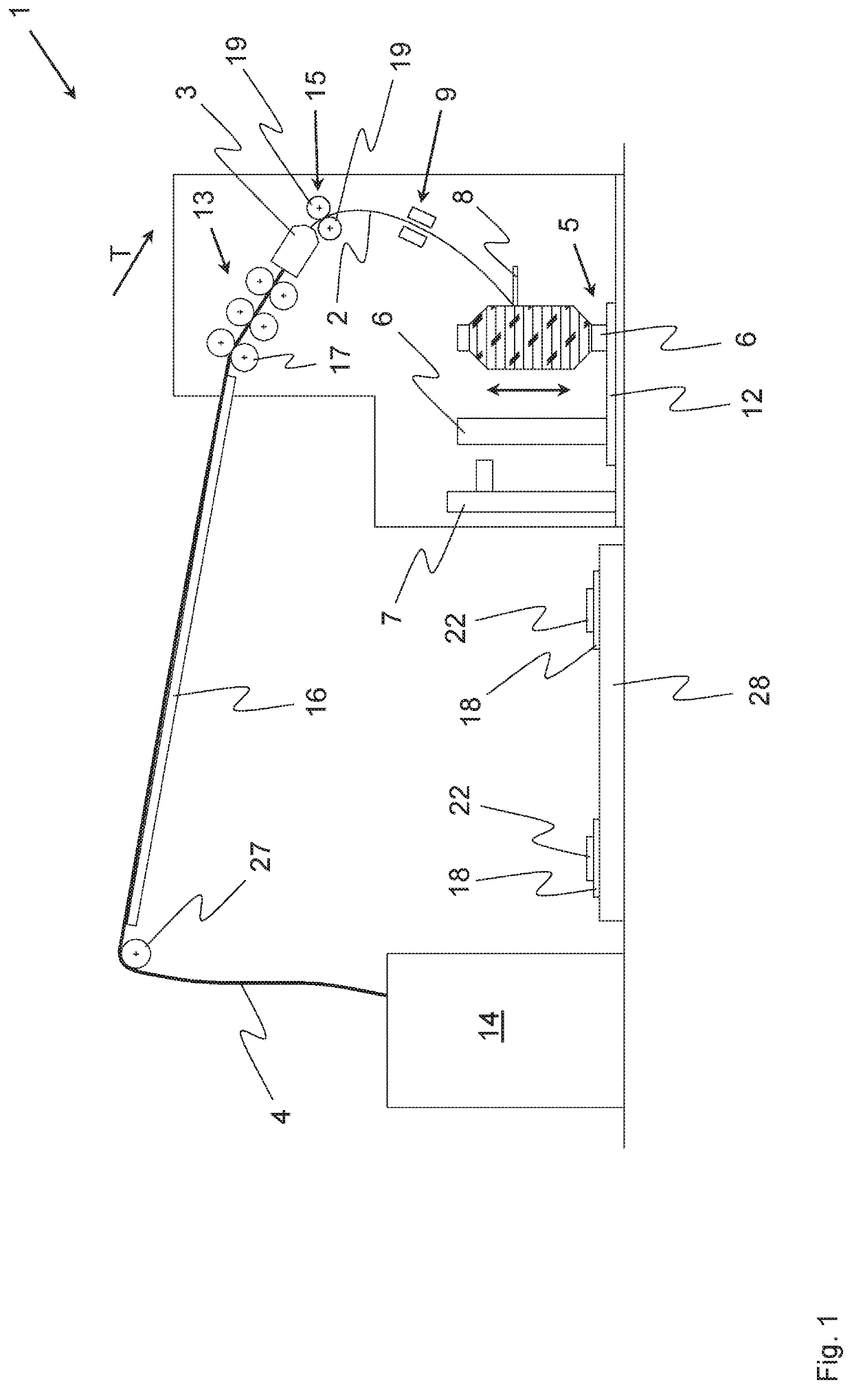
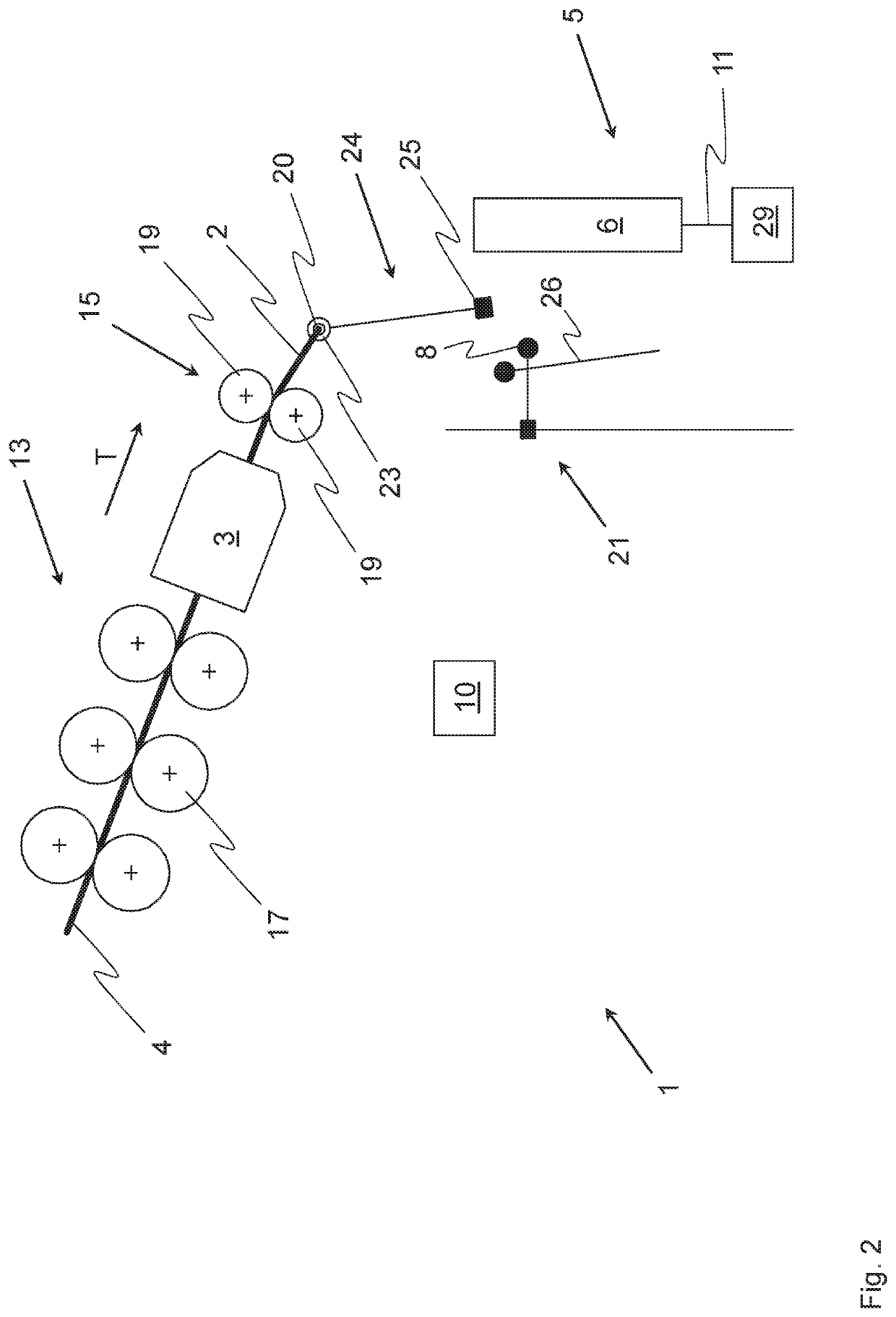
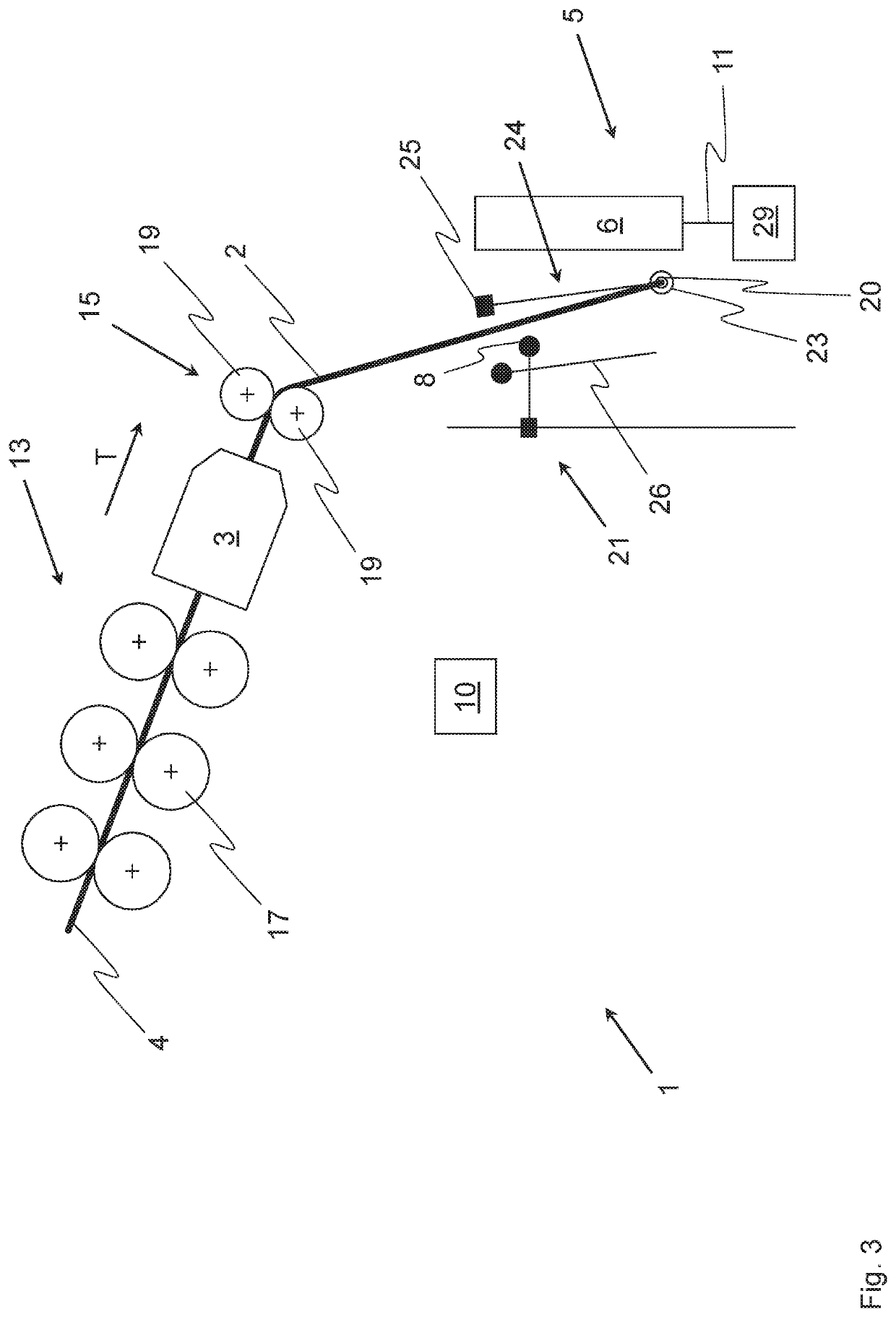
[0033]FIG. 1 is a schematic side view of a textile machine according to the invention in the form of an air-jet spinning machine 1 that serves as an example of such a textile machine and produces roving 2. The air-jet spinning machine 1 preferably comprises a drafting system 13 with a plurality of corresponding drafting system rollers 17 (only one of the six illustrated drafting system rollers 17 is provided with a reference number) that is supplied with a fiber bundle 4, for insta...


PUM

PropertyMeasurementUnit
physical characteristicsaaaaaaaaaa
strengthaaaaaaaaaa
cohesionaaaaaaaaaa

Abstract

During normal operation of a textile machine, a fiber bundle is supplied to a consolidating means to produce a roving having a protective twist, the roving wound onto a tube with a winding device. The roving downstream of the consolidating means is monitored for whether the roving is being produced by the consolidating means or whether the roving produced by the consolidating means is being wound onto the tube. In no roving is being produced or the roving produced by the consolidating means is not being wound onto the tube, an interruption of the normal operation of the textile machine is initiated and the tube partly loaded with roving by the winding device prior to the interruption is replaced with an empty tube during a tube changing process. The consolidating means is started up and the roving produced thereby is brought into contact with the empty tube. Normal operation is resumed and the roving is wound onto the empty tube.

Description

FIELD OF THE INVENTION[0001]The present invention relates to a method for operating a textile machine that produces roving, wherein during normal operation a fiber bundle is supplied to at least one consolidating means of the textile machine and a roving having a protective twist is produced from the fiber bundle by means of the consolidating means. After leaving the consolidating means and using a winding device arranged downstream of the consolidating means in a transport direction of the roving, the roving is wound onto a tube. A sensor system monitors whether a roving is being produced by the consolidating means and / or whether the roving produced by the consolidating means is being wound onto the tube.[0002]Furthermore, a textile machine is suggested for producing roving having at least one consolidating means, by means of which during normal operation a roving having a protective twist is produced from a fiber bundle supplied to the consolidating means. In addition, the textile...

Claims


Application Information

Patent Timeline
Patent Type & Authority Patents(United States)
IPC IPC(8): B65H63/02D01H7/92D01H9/04B65H54/02B65H63/024D01H9/16B65H67/04D01H13/16D01H1/115
CPCD01H9/04B65H63/024D01H9/16B65H67/0422B65H54/02D01H7/92B65H63/02B65H67/04D01H13/16D01H1/115B65H2701/31B65H2701/311
Inventor GRIESSHAMMER, CHRISTIAN
Owner MASCHINENFABRIK RIETER AG
Learn More