Intermediate case for an aircraft turbomachine comprising a lubricant passage end-piece connected to a case vane by a connection piece

a technology of lubricant passage and connection piece, which is applied in the direction of machines/engines, stators, liquid fuel engines, etc., can solve the problem of limiting static indeterminacy in the assembly of the vane, and achieve the effect of flexible assembly, reduced case size, and easy fabrication

Active Publication Date: 2020-06-02
SN DETUDE & DE CONSTR DE MOTEURS DAVIATION S N E C M A
View PDF7 Cites 0 Cited by
  • Summary
  • Abstract
  • Description
  • Claims
  • Application Information

AI Technical Summary

Benefits of technology

[0009]The invention is remarkable firstly in that it can reduce the size of the case in the radial direction due to the circumferential offset between the end-piece and the vane root lubricant passage orifice. The layout advantageously becomes easier, even close to the flow splitter.
[0010]The invention also provides an ingenious solution to the search for optimisation mentioned above. Apart from being easy to fabricate for example by machining, the connection piece forms an intermediate connection part between the vane root and the duct supported by the hub, thus providing flexibility in the assembly. The position of the connection part relative to the vane and the hub can be adjusted to a certain extent, such that this connection part is optimally placed relative to these two elements. The flexibility provided by this arrangement not only facilitates assembly and disassembly, but it also limits static indeterminacy in assembly of the vane. This is particularly advantageous when the vane performs an additional structural function of transferring forces towards an engine-to-aircraft attachment. In this case, the forces then pass mainly through the vane-to-hub attachments, and not through the lubricant passage end-pieces.
[0011]With the proposed design, the vane can also be easily assembled and disassembled, and maintenance of each end-piece is also facilitated if the end-piece is damaged.

Problems solved by technology

The flexibility provided by this arrangement not only facilitates assembly and disassembly, but it also limits static indeterminacy in assembly of the vane.

Method used


Image

  • Intermediate case for an aircraft turbomachine comprising a lubricant passage end-piece connected to a case vane by a connection piece
  • Intermediate case for an aircraft turbomachine comprising a lubricant passage end-piece connected to a case vane by a connection piece
  • Intermediate case for an aircraft turbomachine comprising a lubricant passage end-piece connected to a case vane by a connection piece

Examples


Embodiment Construction

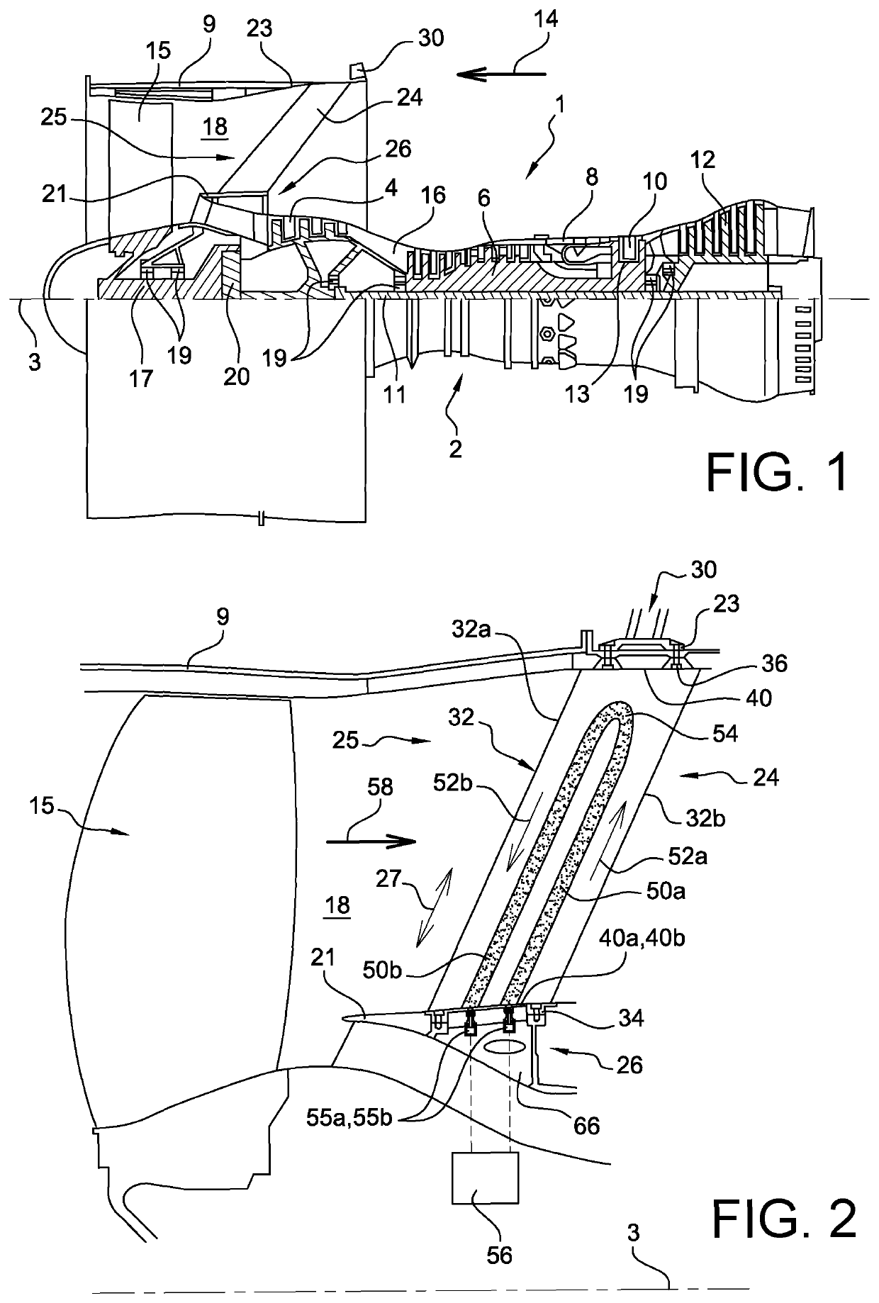
[0045]With reference to FIG. 1, the figure represents a twin-flow twin-spool turbojet, for example with a high dilution ratio. The turbojet 1 conventionally comprises a gas generator 2 with a low pressure compressor 4 on one side and a low pressure turbine 12 on the other side, this gas generator 2 comprising a high pressure compressor 6, a combustion chamber 8 and a high pressure turbine 10. In the following, the terms “forward” and aft” are considered along a direction 14 opposite to the main flow direction of gases in the turbojet, this direction 14 being parallel to the longitudinal axis 3 of the turbojet. On the other hand, the terms “upstream” and “downstream” are considered along the main flow direction of gases within the turbojet.

[0046]The low pressure compressor 4 and the low pressure turbine 12 form a low pressure case, and are connected to each other through a low pressure shaft 11 centred on the axis 3. Similarly, the high pressure compressor 6 and the high pressure tur...


PUM


Abstract

The invention relates to an intermediate case for a twin spool turbomachine for an aircraft, comprising at least one lubricant passage and piece (88a) associated with at least one of its vanes (24), comprising a lubricant passage (98a) extending along a passage axis (134a) and opening up into the lubricant duct (55a). The passage axis (134a) and the orifice axis (140a) are also at a spacing from each other along a circumferential direction (91), and a connection piece (125a) through which a connection conduit (142a) passes is firstly partially housed in the vane root (34) so as to create a communication between the connection duct (142a) and the lubricant passage orifice (124a), and secondly is partially housed in an end-piece support device (108a) or in the lubricant passage end-piece (88a), such that the connection conduit (142a) communicates with the lubricant passage (98a) in the end-piece.

Description

TECHNICAL DOMAIN[0001]This invention relates to the field of twin-spool turbomachines for aircraft, and particularly the design of the intermediate case integrating outlet guide vanes formed in the fan air stream of the turbomachine. Such “Outlet Guide Vanes” (OGV) are designed to straighten the air flow at the outlet from the fan.STATE OF PRIOR ART[0002]On some twin-spool turbomachines, it is known that outlet guide vanes can be installed downstream from the fan to straighten the outlet flow from the fan, and possibly also to perform a structural function. This structural function is intended to transfer forces from the centre of the turbomachine to an outer shell located along the prolongation of the fan case. In this case, an engine attachment is conventionally formed on or close to this outer shell, to form the attachment between the turbomachine and an aircraft attachment pylon.[0003]It was also recently disclosed that the outlet guide vanes can be expected to perform an additi...

Claims


Application Information

Patent Timeline
Patent Type & Authority Patents(United States)
IPC IPC(8): F01D9/06F01D25/18F04D29/54F02C7/18F04D29/58F02K3/115F04D29/063F01D5/18F01D9/04F01D25/12F02K3/06
CPCF01D5/185F01D9/065F02K3/06F01D25/18F04D29/542F01D25/12F01D9/042F04D29/584F02C7/18F04D29/063F02K3/115Y02T50/671F05D2240/12F05D2220/32F05D2260/98F05D2240/14Y02T50/676F05D2260/213Y02T50/60
Inventor ZACCARDI, CÉDRICJABLONSKI, LAURENTJACQUEMARD, CHRISTOPHE PAULPERDRIGEON, CHRISTOPHE MARCEL LUCIEN
Owner SN DETUDE & DE CONSTR DE MOTEURS DAVIATION S N E C M A
Why Eureka
Try Eureka