
Signal-preserving noise decorrelation

a noise decorrelation and signal technology, applied in the field of noise decorrelation, can solve the problems of undesirable properties of decorrelated channels, very different sensitivities of decorrelated channels, etc., and achieve the effect of improving the noise decorrelation of mr measurement signals

Active Publication Date: 2020-05-12
SIEMENS HEALTHCARE GMBH
View PDF1 Cites 0 Cited by
  • Summary
  • Abstract
  • Description
  • Claims
  • Application Information

AI Technical Summary

Benefits of technology

[0007]Accordingly, there is a need for an improved method for noise decorrelation of MR measurement signals, which overcomes the above-mentioned disadvantages. It is, therefore, an objective of the present application to provide a method, an MR apparatus, and a non-transitory, computer-readable data storage medium, which provide an improved noise decorrelation of MR measurement signals from multiple MR detector channels.
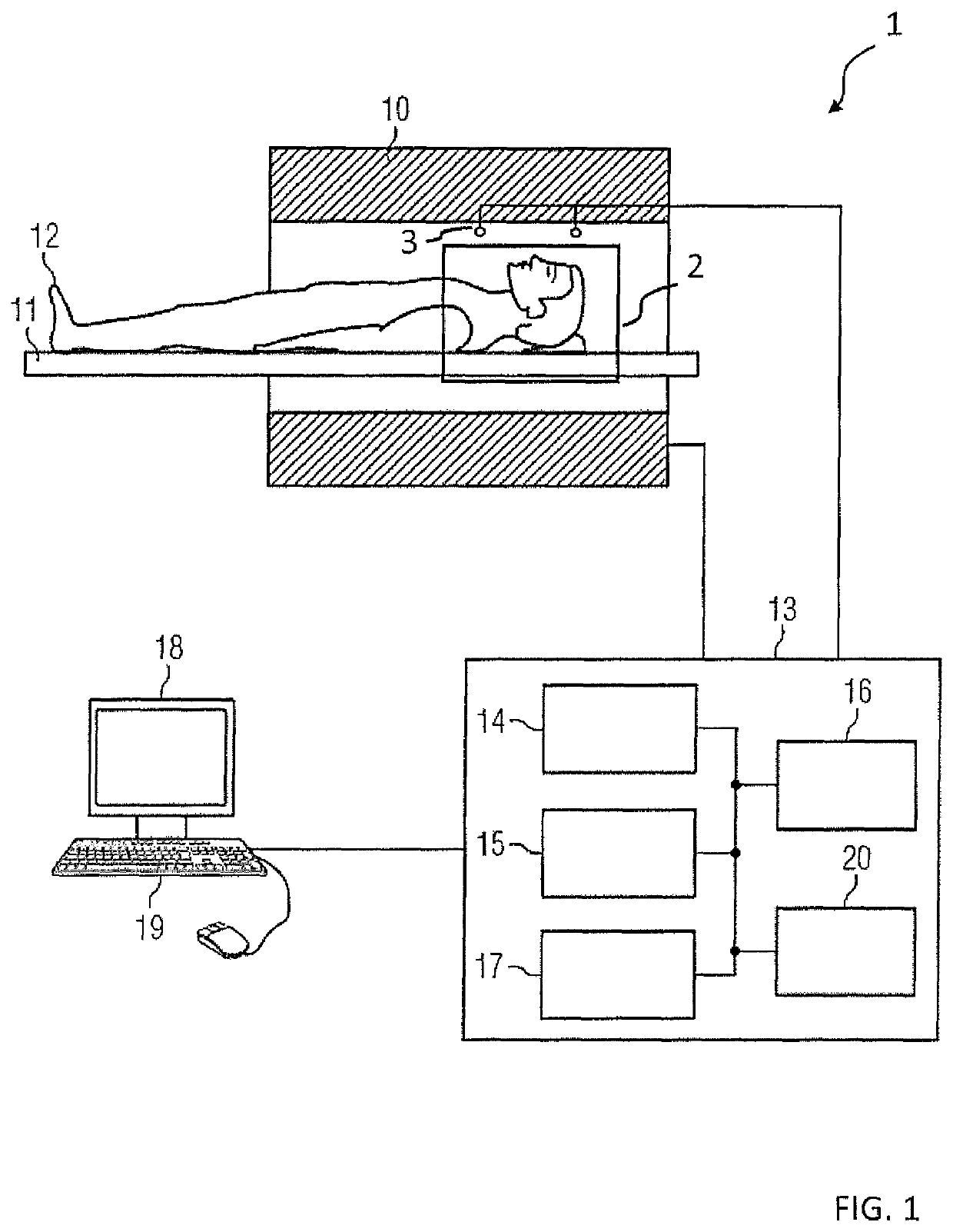
[0009]Thereby, an improved method for noise decorrelation of MR measurement signals is provided, which provides noise-decorrelated channels with similar properties as the original, physical channels. In particular, sensitivities of the decorrelated channels are similar to the original channels, wherein sensitivity distributions have similar phases. For example, such decorrelated MR measurement signals of an individual detector (antenna) channel can still be associated to a specific spatial region of the examination region. This enables noise decorrelation for previously impossible cases such as “mode matrix” systems, as described in U.S. Pat. No. 7,098,659 B2, and pre-compressed channel sets. Other unfavorable properties of the sensitivities of decorrelated channels may be minimized simultaneously.
[0010]Accordingly, the method enables better MR image quality and shorter MR measurement and image reconstruction times compared to current methods for noise decorrelation of MR measurement signals. In particular, noise decorrelation of particular channels, e.g. the “CP” or “primary” modes of an original TIM system by Siemens Healthcare AG, can be performed, with the properties of the individual coil sensitivities of the decorrelated channels being initially unchanged.

Problems solved by technology

Further, a drawback of picking the noise decorrelation matrix arbitrarily is that the sensitivities of the decorrelated channels may look very different from the original channels.
Additionally, the decorrelated channels may have other undesirable properties, such as sensitivity distributions with a strongly varying phase.

Method used


Image

  • Signal-preserving noise decorrelation
  • Signal-preserving noise decorrelation
  • Signal-preserving noise decorrelation

Examples


Embodiment Construction

[0019]In the following, embodiments of the invention will be described in detail with reference to the accompanying drawings. It is to be understood that the following description of embodiments is not to be taken in a limiting sense. The scope of the invention is not intended to be limited by the embodiments described hereinafter or by the drawings, which are taken to be illustrative only.

[0020]The drawings are to be regarded as being schematic representations and elements illustrated in the drawings are not necessarily shown to scale. Rather, the various elements are represented such that their function and general purpose become apparent to a person skilled in the art. Any connection or coupling between functional blocks, devices, components, modules or other physical or functional units shown in the drawings or described herein may also be implemented by an direct or indirect, connection or coupling. A coupling between components may be established wired or over a wireless conne...


PUM


Abstract

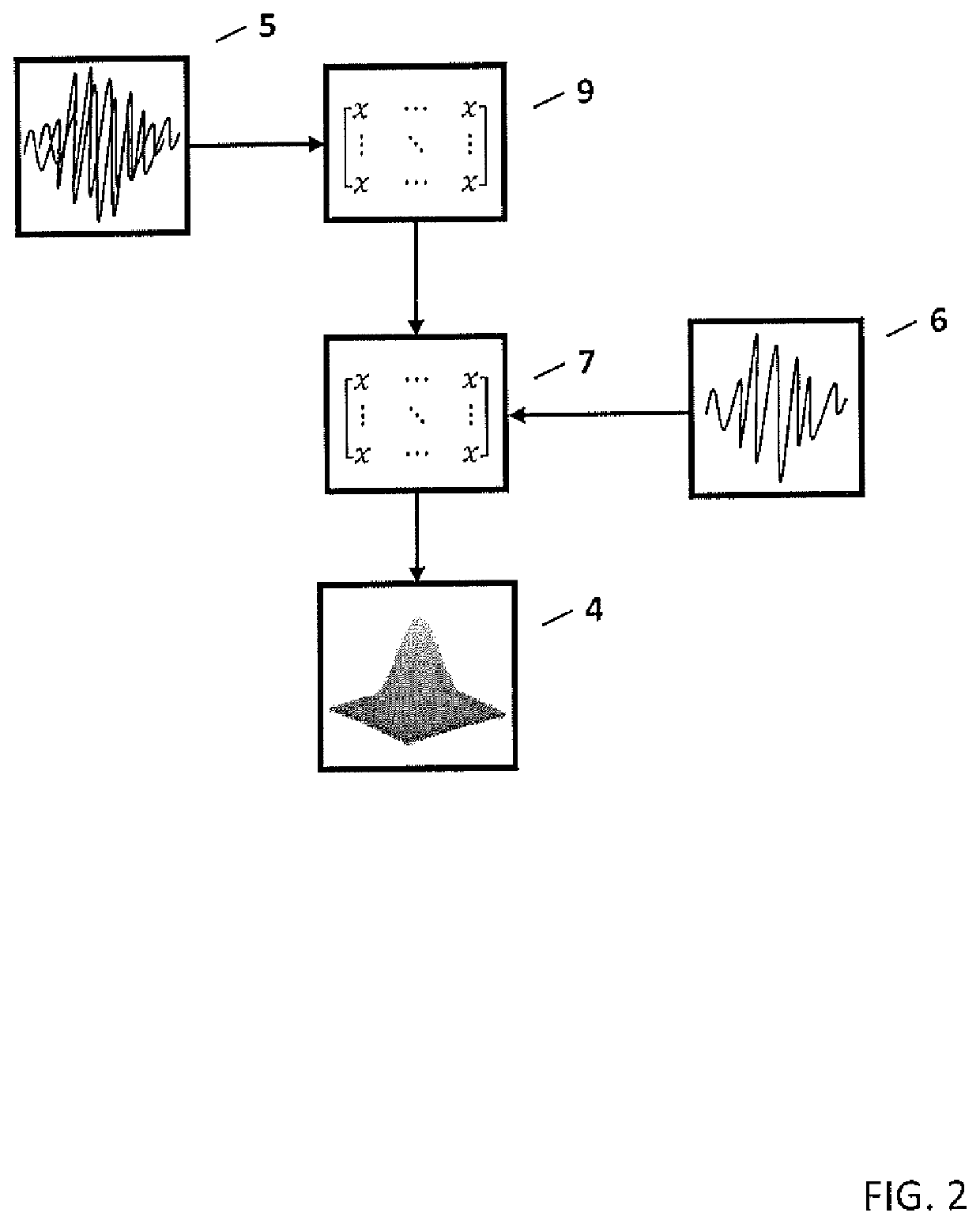
In a method and apparatus for noise decorrelation of magnetic resonance (MR) measurement signals acquired by multiple detectors of an MR apparatus, which are disturbed by additive noise, noise signals and reference signals of the multiple detectors are used to determine an improved noise decorrelation matrix, which removes a noise correlation in the MR measurement signals of the multiple detectors.

Description

RELATED APPLICATION[0001]The present application claims the benefit of the filing date of Provisional Application Control No. 62 / 585,069, filed on Nov. 13, 2017, the contents of which are incorporated herein by reference.BACKGROUND OF THE INVENTIONField of the Invention[0002]The present invention concerns noise decorrelation and in particular to a method for noise decorrelation of magnetic resonance (MR) measurement signals acquired by multiple detectors of an MR system. The present invention also concerns a computer, an MR apparatus, and a non-transitory, computer-readable data storage medium encoded with programming instructions that implement such a method.Description of the Prior Art[0003]Noise decorrelation of MR measurement signals detected or received in multiple MR measurement channels is also referred to as noise whitening transformation. As a preprocessing step, it is necessary for optimal performance of subsequent signal processing, e.g. iPAT or channel combination. Furth...

Claims


Application Information

Patent Timeline
Patent Type & Authority Patents(United States)
IPC IPC(8): G01R33/56G01R33/3415G01R33/561
CPCG01R33/5608G01R33/5611G01R33/3415
Inventor KANNENGIESSER, STEPHANMAILHE, BORIS
Owner SIEMENS HEALTHCARE GMBH
Learn More