System and method for keyless firearm lock
a keyless and firearm technology, applied in the field of keyless firearm locks, can solve the problems of easy deformation or even breakage, poor anti-theft properties of the key itself, and tight restrictions on the use of the gun, and achieve the effect of simple unlocking and secure us
- Summary
- Abstract
- Description
- Claims
- Application Information
AI Technical Summary
Benefits of technology
Problems solved by technology
Method used
Image
Examples
example 1
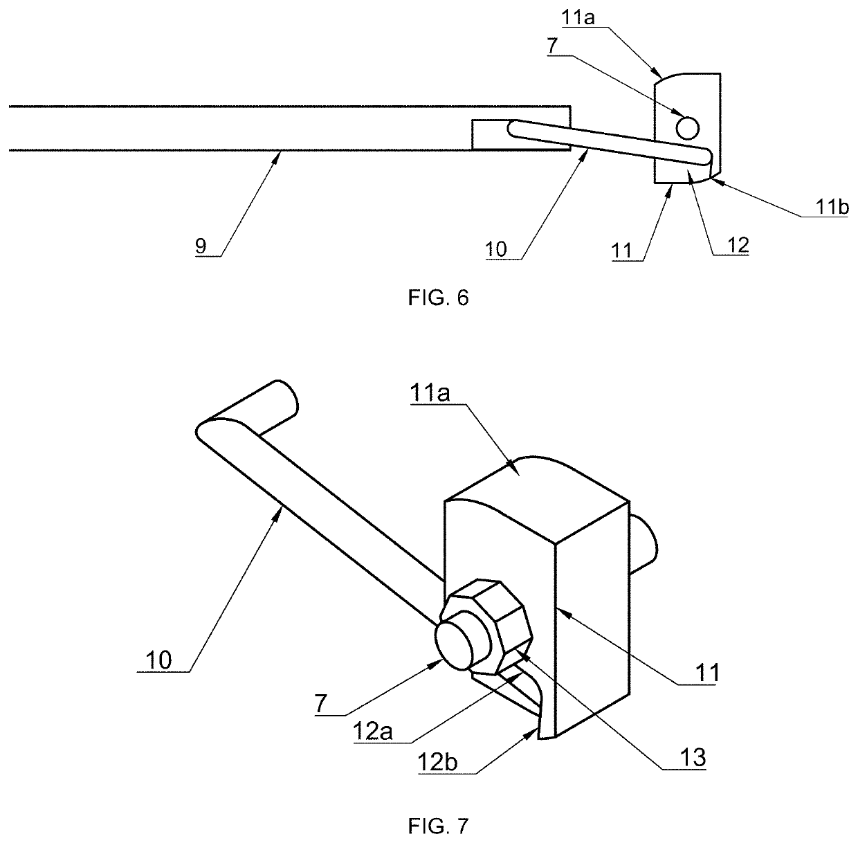
[0094]The locking component is formed in one example with a generally cuboid shape. More specifically, the locking component is preferably shaped in this example with a suitably deformed cuboid body generally similar to a rectangular parallelepiped. The deformation may include, for example, altering one or several straight edge surfaces of the rectangular parallelepiped form to a transitional curvilinear arc, or altering one or several planes of the rectangular parallelepiped to a circular arc surfaces, etc. FIG. 7 is a schematic perspective view illustrating a sample structure of such rectangular parallelepiped-like locking component 11. FIG. 7 shows the rotation shaft 7, the connecting rod 10, the locking component 11, and the positioning units 12a, 12b.
[0095]The lateral / cross dimension of the locking component 11 perpendicular to the longest side in this example is sufficiently small that the locking component 11 may fit inside of the second outer casing when the direction of it...
example 2
[0098]The locking component is formed in another example with a generally ellipsoid shape. More specifically, the locking component is preferably shaped in this example with a partially ellipsoid body. In the example shown, at least one of the edge surfaces at the long axis ends of the ellipsoid form an end face for engaging an inner surface or structure of the given firearm when the locking component 11 is in its locked position. FIG. 8 is a schematic perspective view which shows the rotation shaft 7, the connecting rod 10, the locking component 11, the concave surface 12, and the positioning units 12a, 12b in this embodiment.
[0099]In this example, the locking component 11 is configured for use within a second outer casing 4 having openings 5a, 5b both above and below. Accordingly, the locking component is formed with two end faces at longitudinally opposed ends along the major axis of the ellipsoid, whose minor axis is configured to be smaller in diameter than the inner diameter o...
PUM
 Abstract
Description
Claims
Application Information
 - R&D
- Intellectual Property
- Life Sciences
- Materials
- Tech Scout
- Unparalleled Data Quality
- Higher Quality Content
- 60% Fewer Hallucinations
Browse by: Latest US Patents, China's latest patents, Technical Efficacy Thesaurus, Application Domain, Technology Topic, Popular Technical Reports.
© 2025 PatSnap. All rights reserved.Legal|Privacy policy|Modern Slavery Act Transparency Statement|Sitemap|About US| Contact US: help@patsnap.com


