Assembly for an aircraft comprising an engine of the “open rotor puller” type and means for attaching the latter to the rigid structure of an attachment pylon

a technology of open rotor pusher and aircraft, which is applied in the field of aircraft, can solve the problems that conventional engines or engines of the “open rotor pusher” type are not suitable, and achieve the effect of limiting the load that the pyramid has to bear

Active Publication Date: 2020-05-12
AIRBUS OPERATIONS (SAS)
View PDF13 Cites 1 Cited by
  • Summary
  • Abstract
  • Description
  • Claims
  • Application Information

AI Technical Summary

Benefits of technology

[0007]It is a particular objective of the invention to afford a simple, economical and effective solution to this problem.
[0019]The overall configuration of the attachment means, particularly the respective positions of the first attachment means, of the second attachment means and of the third attachment means, allows effective transmission of engine forces to the rigid structure of the attachment pylon while at the same time allowing the center of gravity of the engine to be shifted significantly forward of this rigid structure.
[0020]The position of the engine attachments that react moment about the engine axis in particular allows this moment to be transmitted directly to the rigid structure and thus makes it possible to limit the load that the pyramid has to bear.

Problems solved by technology

However, in the case of engines of the “open rotor puller” type, in which the pair of unducted contrarotating rotors is positioned forward of the gas generator, the techniques applied to conventional engines or to engines of the “open rotor pusher” type are not suitable.

Method used


Image

  • Assembly for an aircraft comprising an engine of the “open rotor puller” type and means for attaching the latter to the rigid structure of an attachment pylon
  • Assembly for an aircraft comprising an engine of the “open rotor puller” type and means for attaching the latter to the rigid structure of an attachment pylon
  • Assembly for an aircraft comprising an engine of the “open rotor puller” type and means for attaching the latter to the rigid structure of an attachment pylon

Examples


Embodiment Construction

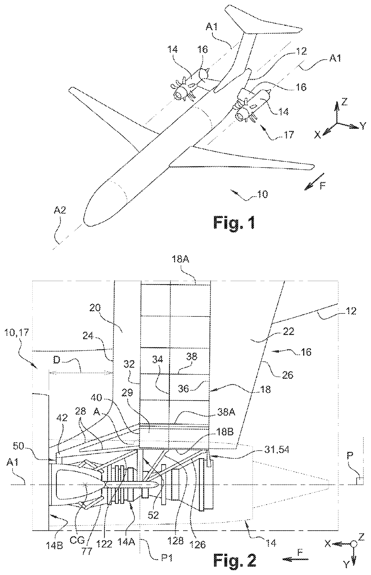
[0039]FIG. 1 illustrates an aircraft 10, the airframe of which comprises a part 12, for example a fuselage tail section part, to which two engines 14 are connected via respective attachment pylons 16 extending laterally from the airframe part 12.

[0040]The aircraft airframe part 12, the engines 14, and the means connecting the engines 14 to the airframe part 12, constitute an assembly for an aircraft 17 within the terminology of the invention.

[0041]In the present description, by convention, the direction X corresponds to the longitudinal direction of each engine 14. This direction X is parallel to a longitudinal axis A1 of each engine 14 and to a longitudinal axis A2 of the aircraft 10, and therefore forms a longitudinal direction of the assembly for an aircraft 17 according to the invention. Furthermore, the direction Y corresponds to the direction oriented transversally or laterally with respect to the aircraft 10 and can also be likened to the transverse direction of the assembly ...


PUM


Abstract

To allow the attachment of an engine of the “Open Rotor Puller” type to the rigid structure of an attachment pylon, an attachment structure comprises a first attachment structure shifted forwards with respect to the center of gravity of the engine and connected to the rigid structure through a pyramid, a second attachment structure laid out at the rear with respect to the first attachment structure and extending in a plane of a first stringer of the rigid structure, and a third attachment structure laid out at the rear with respect to the second attachment structure. The second attachment structure comprises two engine attachments for recovering the moment along the axis of the engine, laid out on either side of a horizontal symmetry plane of the engine.

Description

CROSS-REFERENCES TO RELATED APPLICATIONS[0001]This application claims the benefit of the French patent application No. 1661659 filed on Nov. 29, 2016, the entire disclosures of which are incorporated herein by way of reference.TECHNICAL FIELD[0002]The present invention relates to the field of aircraft and relates more particularly to the attaching of an engine to a part of an aircraft airframe such as an aircraft fuselage tail section, the engine being of the “open rotor puller” type, namely comprising a gas generator and a receiver with a pair of contrarotating unducted rotors positioned forward of the gas generator.BACKGROUND OF THE INVENTION[0003]There are a certain number of known approaches for supporting conventional aircraft engines mounted beneath the wings or at the tail section of the fuselage. Techniques have also been developed for supporting engines of the “open rotor pusher” type, namely those comprising a gas generator and a receiver having a pair of contrarotating un...

Claims


Application Information

Patent Timeline
Patent Type & Authority Patents(United States)
IPC IPC(8): B64D27/20B64D27/26
CPCB64D27/20B64D27/26B64D2027/268B64D2027/262F02C7/24F01D17/085G01K1/08G01K13/02G01K13/024B64D2027/005G01K1/12G01K1/20G01K7/04G01K7/10F01D17/02F05D2260/80G01K1/14
Inventor BOUCHET, ERICCOLMAGRO, JÉRÔMENANDA, ROHANHERNANDEZ PEREZ, MISAEL
Owner AIRBUS OPERATIONS (SAS)
Why Eureka
Try Eureka