
Process and device for rapid torrefaction of biomass

a technology of biomass and torrefaction, which is applied in the direction of adaptive control, process and machine control, instruments, etc., can solve the problems of difficult and thus expensive to reduce the size of biomass particles below one centimeter, undesirable agglomeration of ground particles, and current technical difficulties similar

Inactive Publication Date: 2017-10-24
COMMISSARIAT A LENERGIE ATOMIQUE ET AUX ENERGIES ALTERNATIVES +1
View PDF14 Cites 0 Cited by
  • Summary
  • Abstract
  • Description
  • Claims
  • Application Information

AI Technical Summary

Benefits of technology

[0021]The aim of the invention is particularly that of providing a simple, economical and effective solution for this problem, and particularly relates to a process for the torrefaction of biomass particles at an optimised temperature to minimise the process time while retaining satisfactory grindability of the torrefied biomass particles.

Problems solved by technology

However, it is difficult and thus expensive to reduce the size of biomass particles below one centimeter, particularly in the case of lignocellulosic biomass, due to the fibrous nature of this biomass.
This fibrous nature is particularly conveyed by the presence of microfibrils liable to promote undesirable agglomeration of the ground particles.
The current technical difficulties are similar to those encountered with the entrained flow reactor, since the biomass needs to be injected with the coal in atomised form.
This renders the particles mechanically weaker, and thus increases the grindability thereof.
However, the time required for conventional torrefaction treatment generates industrial costs for which the possibility of reducing same is desirable.
For this reason, obtaining particles of sufficiently small sizes for applications such as those mentioned above, requires more elaborate grinding and thus proves to be more costly.

Method used

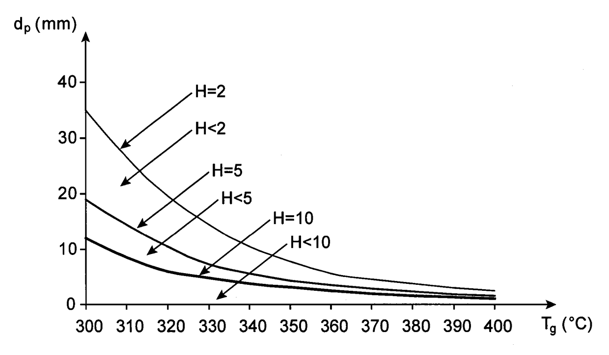
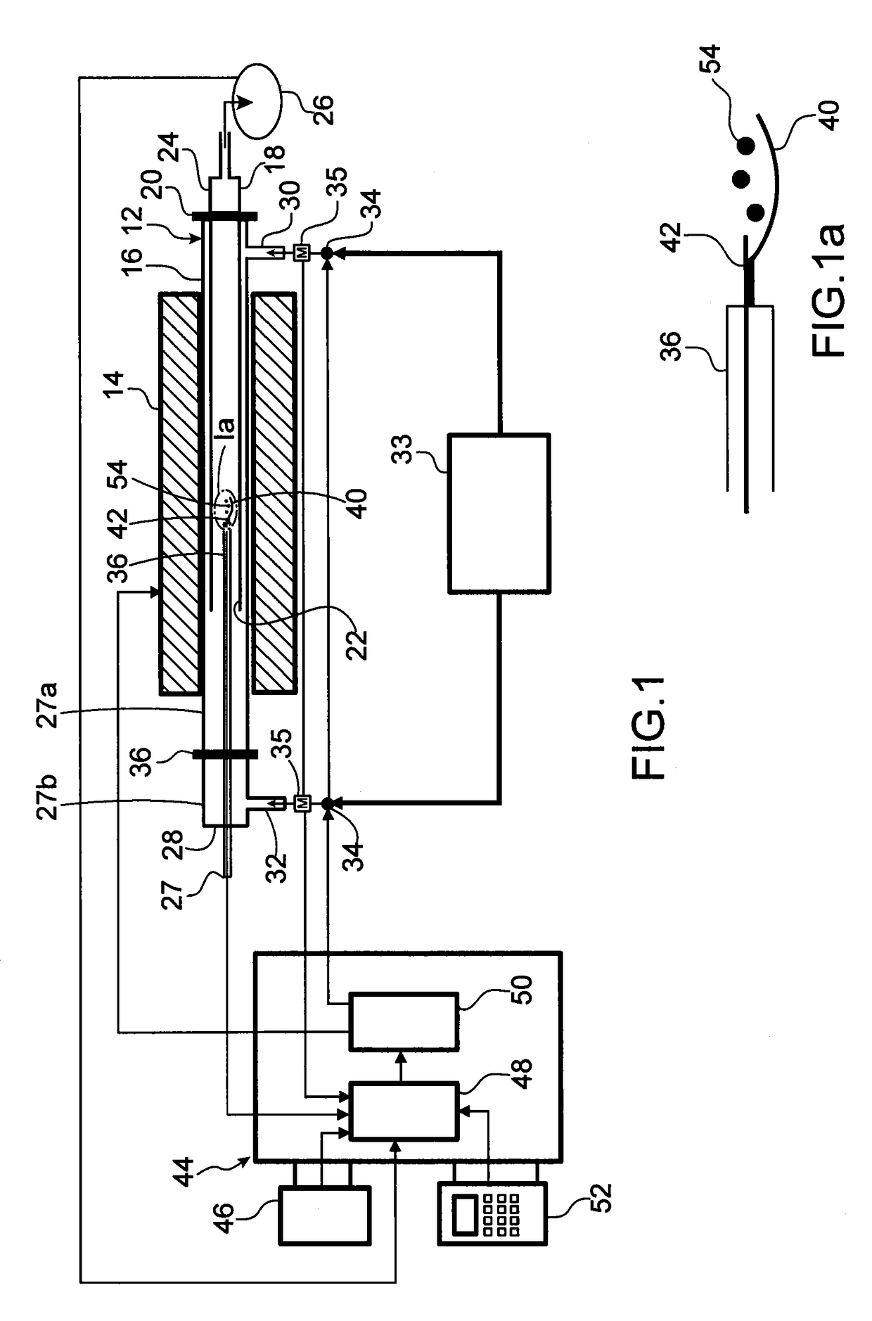
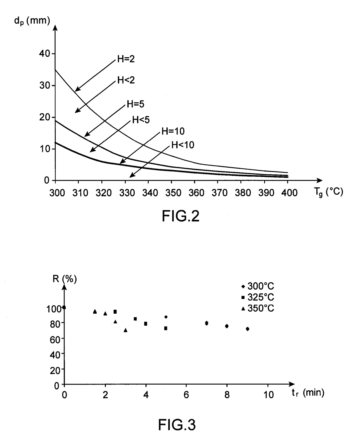

Image

  • Process and device for rapid torrefaction of biomass
  • Process and device for rapid torrefaction of biomass
  • Process and device for rapid torrefaction of biomass

Examples


first embodiment

[0066]This formula thus enables a superior estimation to the formula used in the invention.

second embodiment

[0067]In this second embodiment of the invention, the external heat transfer coefficient hconv is preferably determined using the Ranz-Marshall correlation, by means of the formula:

[0068]hconv=λgdp⁢(2+0.6⁢⁢Rep1 / 2·Pr1 / 2)

[0069]wherein:[0070]Rep is the Reynolds number determined using the formula:

[0071]Rep=ρg×Vg×dpμg;[0072]Pr is the Prandtl number determined using the formula:

[0073]Pr=μg×Cpgλg;

[0074]where:[0075]ρp is the volumetric mass density of the fluid;[0076]μg is the viscosity of the fluid;[0077]λg is the thermal conductivity of the fluid;[0078]Cpg is the specific heat of the fluid;[0079]Vg is a mean velocity of the fluid.

[0080]Furthermore, the reaction rate constant kt is determined on the basis of a kinetic model of the torrefaction reaction, and is dependent on the type of torrefied biomass.

[0081]As a general rule, the torrefaction time tr is advantageously determined according to the torrefaction temperature Tg and the target value of the final mass yield R of the torrefactio...


PUM

PropertyMeasurementUnit
temperature Tgaaaaaaaaaa
mean diameter dpaaaaaaaaaa

Abstract

A process for controlling a unit for torrefaction of biomass particles including: measurement of a mean diameter of the biomass particles; as a function of the mean diameter, calculation of a maximum torrefaction temperature for which the ratio of a characteristic time of the torrefaction to a characteristic time of the heat transfer at the level of the particles is equal to a minimum value; adjusting the torrefaction temperature to a value less than or equal to the maximum torrefaction temperature; adjusting the torrefaction time to a value such that the final yield by weight of the torrefaction is equal to a predefined target value.

Description

FIELD OF THE INVENTION[0001]The present invention relates to the field of thermochemical biomass recovery.[0002]It relates to a biomass particle heat treatment process, of the type known as torrefaction. Such a treatment is suitable for preparing a biomass load with a view to facilitating the fractionation thereof by grinding to prepare same for:[0003]gasification in an entrained flow reactor;[0004]co-combustion with coal.[0005]The term “particles” denotes any type of solid biomass pieces, grains, chips, fragments or debris.[0006]The term biomass denotes any type of material of plant, animal or fungal origin, suitable for becoming an energy source by means of combustion.[0007]The invention relates particularly, but not exclusively, to the torrefaction of lignocellulosic biomass, such as wood.[0008]It particularly relates to a process for controlling a biomass particle torrefaction unit wherein the particles are torrefied for a torrefaction time tr in a fluid, preferably a gas, heate...

Claims


Application Information

Patent Timeline
Patent Type & Authority Patents(United States)
IPC IPC(8): G05B13/04C10B53/02C10L9/08
CPCG05B13/041C10B53/02C10L9/083Y02E50/15C10L2290/58C10L2290/60Y02E50/14C10L2250/06Y02E50/10
Inventor NOCQUET, TIMOTHEECOMMANDRE, JEAN-MICHELDUPONT, CAPUCINE
Owner COMMISSARIAT A LENERGIE ATOMIQUE ET AUX ENERGIES ALTERNATIVES
Learn More