Mortise jig for a plunge router

a plunge router and mortise jig technology, applied in the field of mortise jigs for plunge routers, can solve the problems of failed connections and difficult access to the flush surface, and achieve the effect of making the same cuts

Active Publication Date: 2020-05-12
MORTISE PRO PLUS LLC
View PDF8 Cites 1 Cited by
  • Summary
  • Abstract
  • Description
  • Claims
  • Application Information

AI Technical Summary

Benefits of technology

[0008]The claimed invention differs from what currently exists. Prior to this invention, woodworkers using other jigs available on the market could cut mortises but did not necessarily make the same cuts as easily from mortise to mortise: a problem that often arises when two mortises are connected via a loose tenon. Often, woodworkers desire the connected pieces of timber to have at least one flush surface. Because few jigs allow for consistent cuts, a flush surface is difficult to obtain. Consequently, woodworkers are required to exert an unnecessarily added level of scrutiny and diligence ensuring consistency while using the present invention, a woodworker can make a series of repeated cuts quickly and consistently. Until a woodworker acquires near “expert skills” over many failed attempts over a long period of time, the ability to cut consistent mortises is a haphazard process that results in failed connections.
[0009]The present invention is a mortise and dowel hole jig for ensuring timely and consistent cuts with a plunge router. The jig mounts to a work table and includes slot(s) to confine the router bit while cutting horizontally and holding the router in place vertically by two router guides. The jig also includes a rear clamp to lock-in-place and serve as a face for one or more pieces of wood; front clamp(s) to secure each piece of wood while making cuts; and a centering tool that enables a woodworker to quickly line up the center point of the piece of wood and determine where to make the desired cut.
[0010]The unique centering tool, in particular, enables a woodworker to quickly line up the center point of the piece of wood and determine where to make the cut. Additionally, the clamping mechanism allows the woodworkers to lock one of the clamps in place for all cuts current and subsequent, and adjust clamps on the other side to allow for pieces of wood to be interchanged as necessary in between cuts.
[0011]The present invention reduces the effort and skills needed to cut the precise length and depth of mortises needed for a successful mortise-tenon connection. The reduced effort results in more successful mortise-tenon connections; less attempts to create connections; improved quality and appearance of the pieces of wood; and significantly less time necessary to cut mortises.

Problems solved by technology

Prior to this invention, woodworkers using other jigs available on the market could cut mortises but did not necessarily make the same cuts as easily from mortise to mortise: a problem that often arises when two mortises are connected via a loose tenon.
Because few jigs allow for consistent cuts, a flush surface is difficult to obtain.
Until a woodworker acquires near “expert skills” over many failed attempts over a long period of time, the ability to cut consistent mortises is a haphazard process that results in failed connections.

Method used


Image

  • Mortise jig for a plunge router
  • Mortise jig for a plunge router
  • Mortise jig for a plunge router

Examples


Embodiment Construction

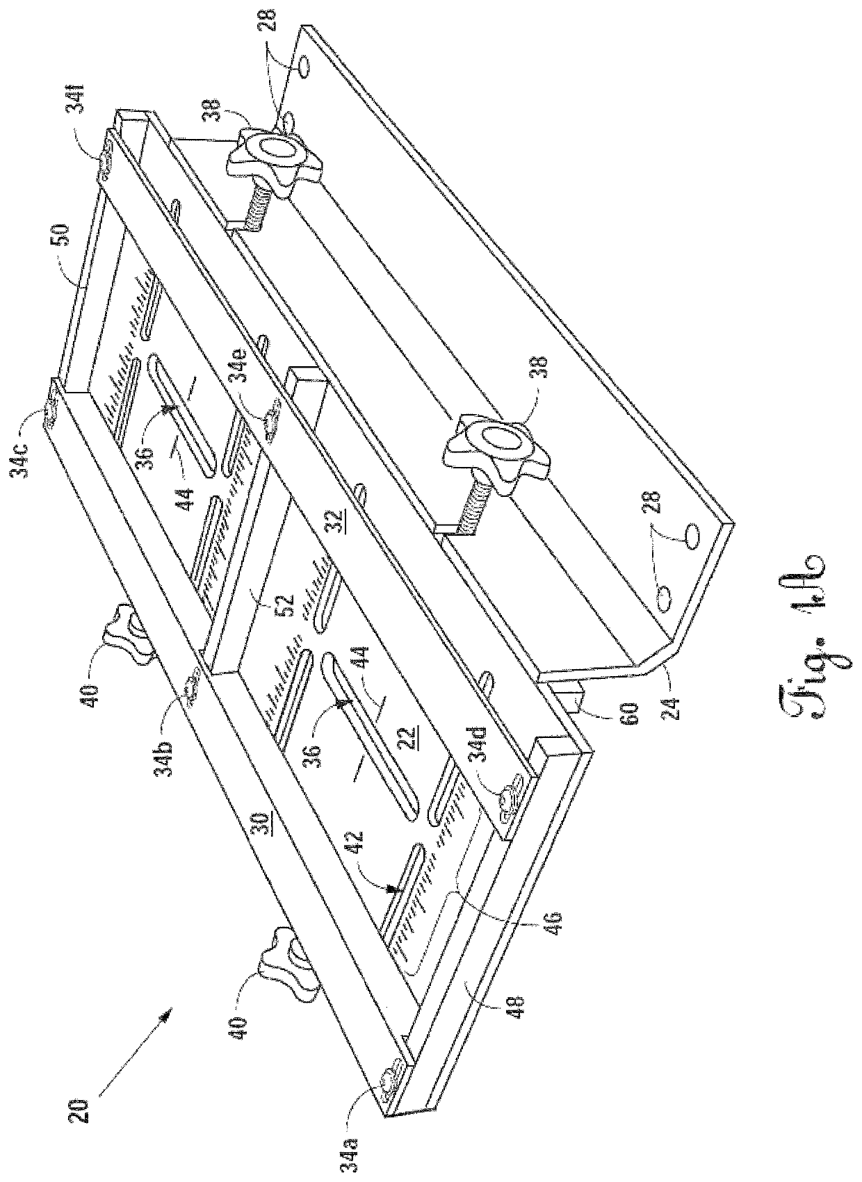
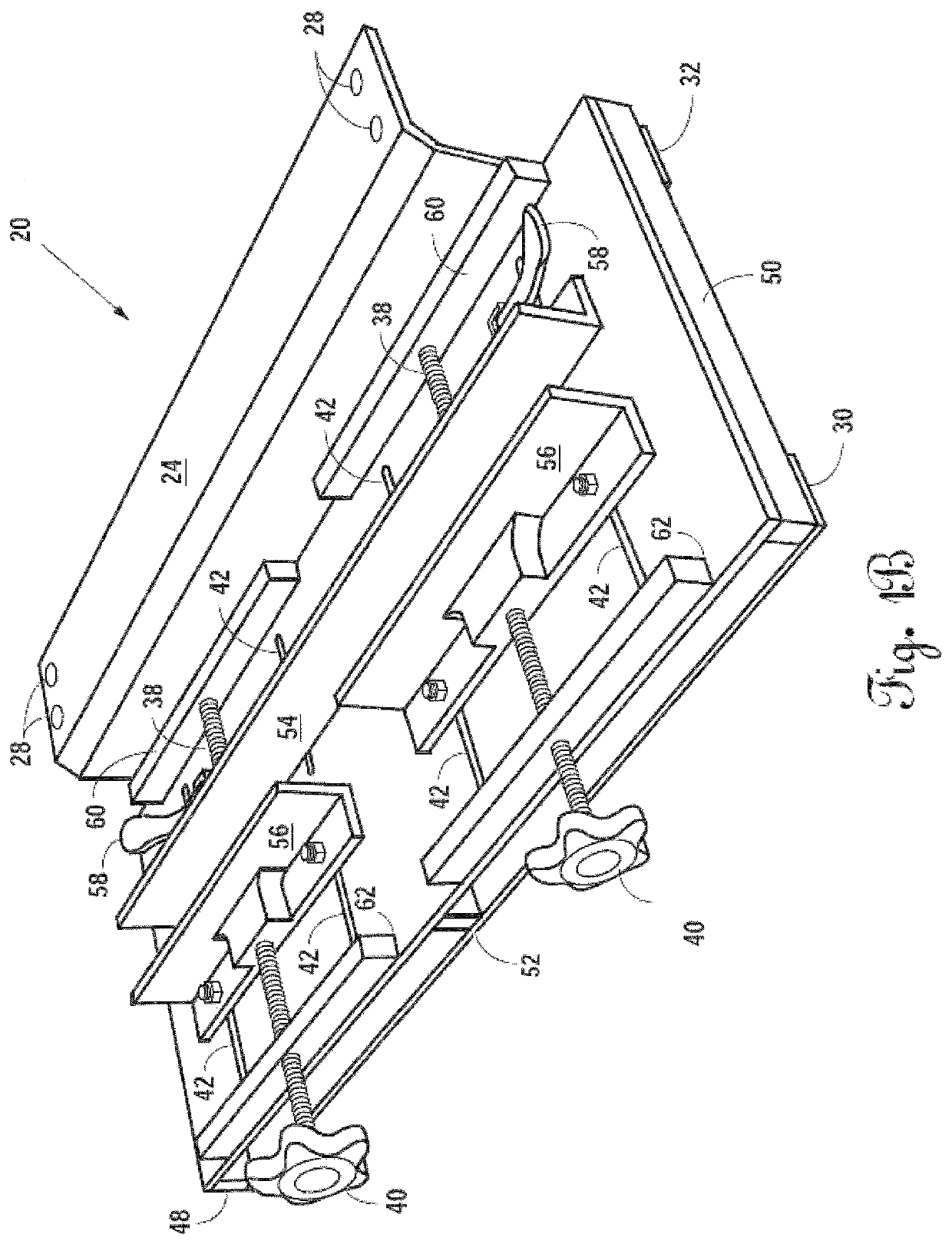
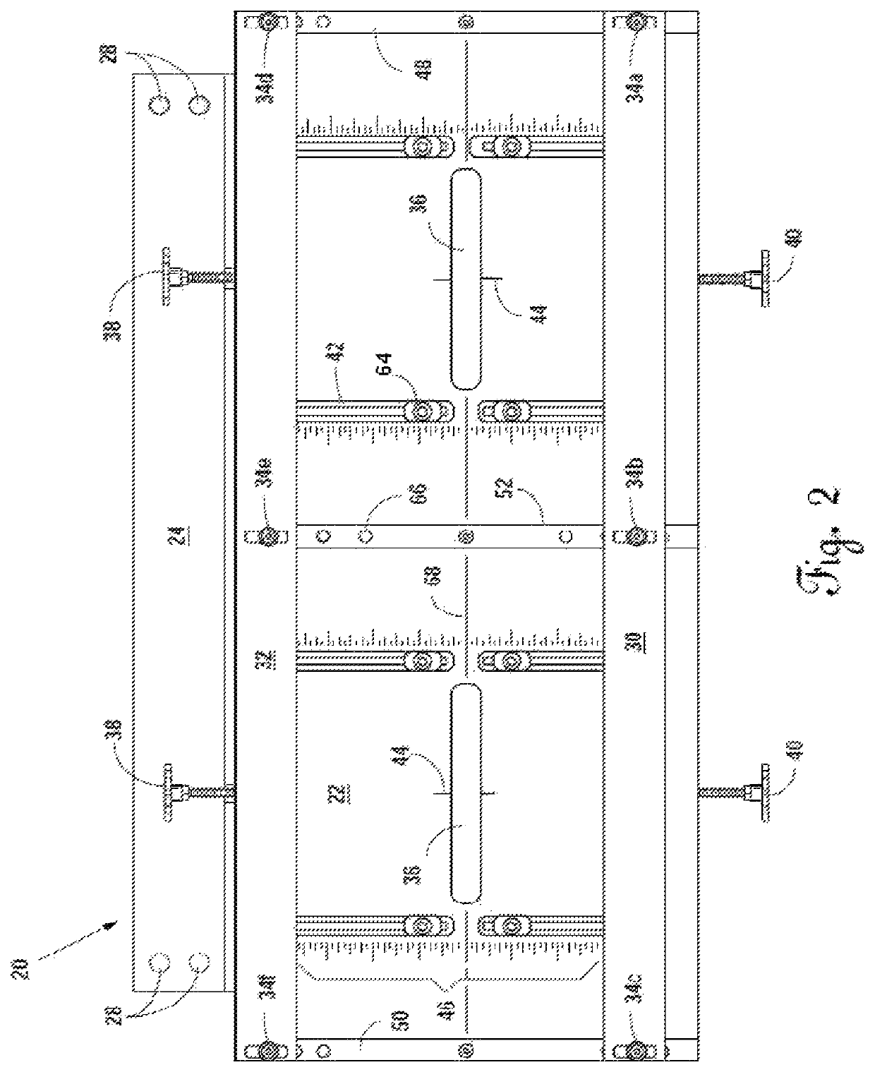
[0020]The embodiment of FIG. 1A illustrates a jig 20 comprising multiple attributes / elements. The jig 20 comprises a working surface 22 having a number of cutouts and other pieces. Affixed to the working surface 22 is a mounting bracket 24. As illustrated in FIG. 1A, mounting bracket 24 is generally perpendicular to the working surface 22. In this particular embodiment, the mounting bracket 24 can be connected and attached to the working surface 22, such that the mounting bracket on one surface can rest just above a work station or a piece of plywood and secured in place with screws, nails, or other hardware or secured through one or more mounting bracket orifices 28. In this illustration, there are four mounting bracket orifices 28. This embodiment of the invention also has a rear router guide 30, and a front router guide 32. The rear router guide 30 and front router guide 32 may be adjusted. Being able to adjust the rear router guide 30 and the front router guide 32 is important f...


PUM

PropertyMeasurementUnit
travel distanceaaaaaaaaaa
shapeaaaaaaaaaa
lengthaaaaaaaaaa

Abstract

A mortise and dowel hole jig for ensuring timely and consistent cuts with a plunge router. The jig mounts to a work table and includes slot(s) to confine the router bit while cutting horizontally and holding the router in place vertically by two router guides. The jig also includes a rear clamp to lock-in-place and serve as a face for one or more pieces of wood; front clamp(s) to secure each piece of wood while making cuts; and a centering tool that enables a woodworker to quickly line up the center point of the piece of wood and determine where to make the desired cut.

Description

CROSS-REFERENCES TO RELATED APPLICATIONS[0001]This application claims the benefit of and priority to U.S. Provisional Application Ser. No. 62 / 081,653, filed Nov. 19, 2014 and entitled Jig for a Plunge Router, which is incorporated by reference herein.FEDERALLY SPONSORED RESEARCH OR DEVELOPMENT[0002]Not applicable.BACKGROUND OF THE INVENTION[0003]1. Field of the Invention[0004]The present invention relates generally to woodworking and using jigs for routing mortises and dowel holes.[0005]2. Description of the Related Art[0006]Connecting pieces of wood is accomplished by a number of techniques. Historically, tenon and mortise and / or dowel connections have been popular with woodworkers for strength and stability. A tenon is a projection on the end of the timber for insertion into a mortise. Tenons are usually taller than they are wide. There are several kinds of tenons, including: stub tenons, through tenons, and loose tenons. A mortise is a cavity cut into a piece of timber to receive...

Claims


Application Information

Patent Timeline
Patent Type & Authority Patents(United States)
IPC IPC(8): B23B47/28B27F1/08B23Q9/00
CPCB27F1/08B23Q9/00B23B47/288B23B2247/12
Inventor SETCHELL, JAYCURRENT, LARRY
Owner MORTISE PRO PLUS LLC
Why Eureka
Try Eureka