Needle assembly with needle shroud and movable needle support

a technology of needle shroud and needle support, which is applied in the direction of infusion needles, intravenous devices, infusion devices, etc., can solve the problem of user's fingertip accidentally coming into contact with the rearward needle tip

Active Publication Date: 2020-05-12
OWEN MUMFORD
View PDF18 Cites 1 Cited by
  • Summary
  • Abstract
  • Description
  • Claims
  • Application Information

AI Technical Summary

Benefits of technology

[0020]The needle shield is coupled to the body and the needle support is captive therebetween. The needle support may therefore be internally located within the needle assembly. Advantageously, embodiments may provide an arrangement in which externally only the relative movement of the needle shield relative to the body is visible and the end user does not need to be aware of the additional movement of the needle support. Further, by providing the needle support internally captive between the body and needle shield, the needle assembly may have only a single external coupling when in the shroud configuration after use which may provide a more robust arrangement.
[0033]The needle support may be mounted within the body. The needle support may be mounted inside forward housing portion of the body in the injection configuration. The needle support may be entirely mounted within a recess formed by the body in the injection configuration. The needle support may be mounted so as to contact a rear wall of the forward housing portion in the injection configuration. The needle portion may be prevented from moving within the body in the injection configuration. The needle support may be restrained against rotation within the body in the injection configuration.
[0039]Movement of the shield to the intermediate position relative to the body may be sufficient to ensure that the rear end of the needle moves to a safe position. Movement of the shield to the intermediate position may ensure that the rear end of the needle moves to a position beyond a radial wall provided in the body.
[0041]The body may include a radial wall. The radial wall may define a separation between a rearward portion configured for removable attachment to an injection device and a forward portion associated with the shield. The wall may include an aperture through which the rearward portion of the needle projects in the injection configuration (and which may also be resiliently engaged by the needle support). In the shroud configuration the rearward end of the needle is forward of the radial wall. Thus, the radial wall may provide a shielding function.
[0044]Upon movement from the injection configuration to the shroud configuration, the needle assembly may lock into the shroud configuration. For example, a snap fit arrangement may prevent reverse movement of the needle shield relative to the body. The needle shield may lock in position when the needle assembly is moved into the shrouded configuration. An audible and / or tactile indication may be provided upon locking of the needle shield. For example, the audible and / or tactile indication may be provided when the needle assembly is in the shroud configuration. The needle assembly may further include a visual indication when the needle assembly is in the shrouded configuration. A visual indicator may be provided on a portion of the shield or body which is only visible when the needle assembly is in the shrouded configuration.
[0066]The body may be provided with a radial wall. When the needle assembly is in the intermediate configuration, the rear end of the needle may be in a position forward of the radial wall. The radial wall may provide a shielding function.

Problems solved by technology

However, the internal diameter of the rearward portion of the hub is defined by the interface with the injection device and, as such, the applicant has recognised that for at least some devices the resulting opening may be of too large a diameter to prevent the risk of a user's fingertip accidentally coming into contact with the rearward needle tip.

Method used


Image

  • Needle assembly with needle shroud and movable needle support
  • Needle assembly with needle shroud and movable needle support
  • Needle assembly with needle shroud and movable needle support

Examples


first embodiment

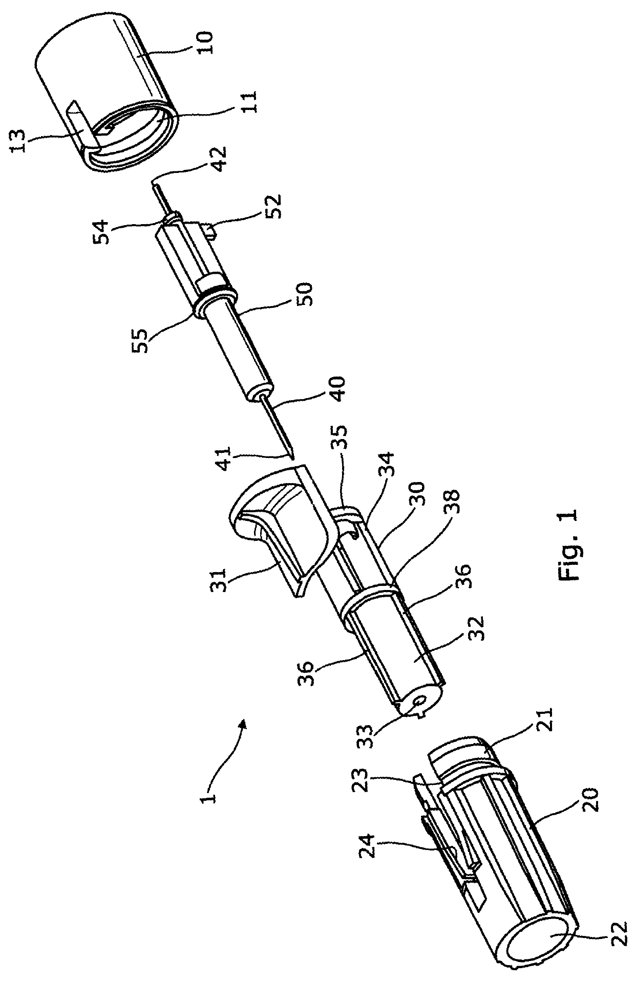
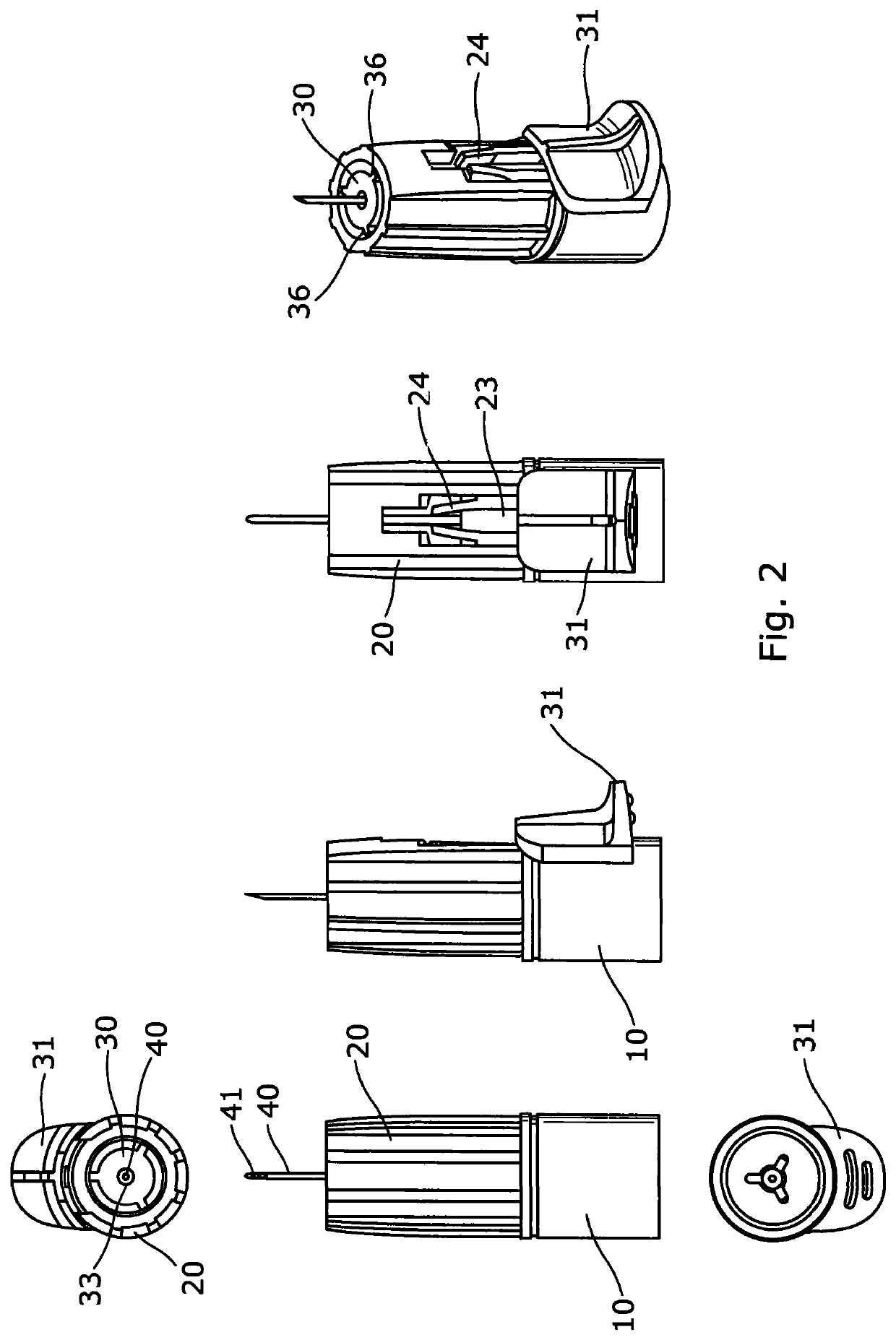
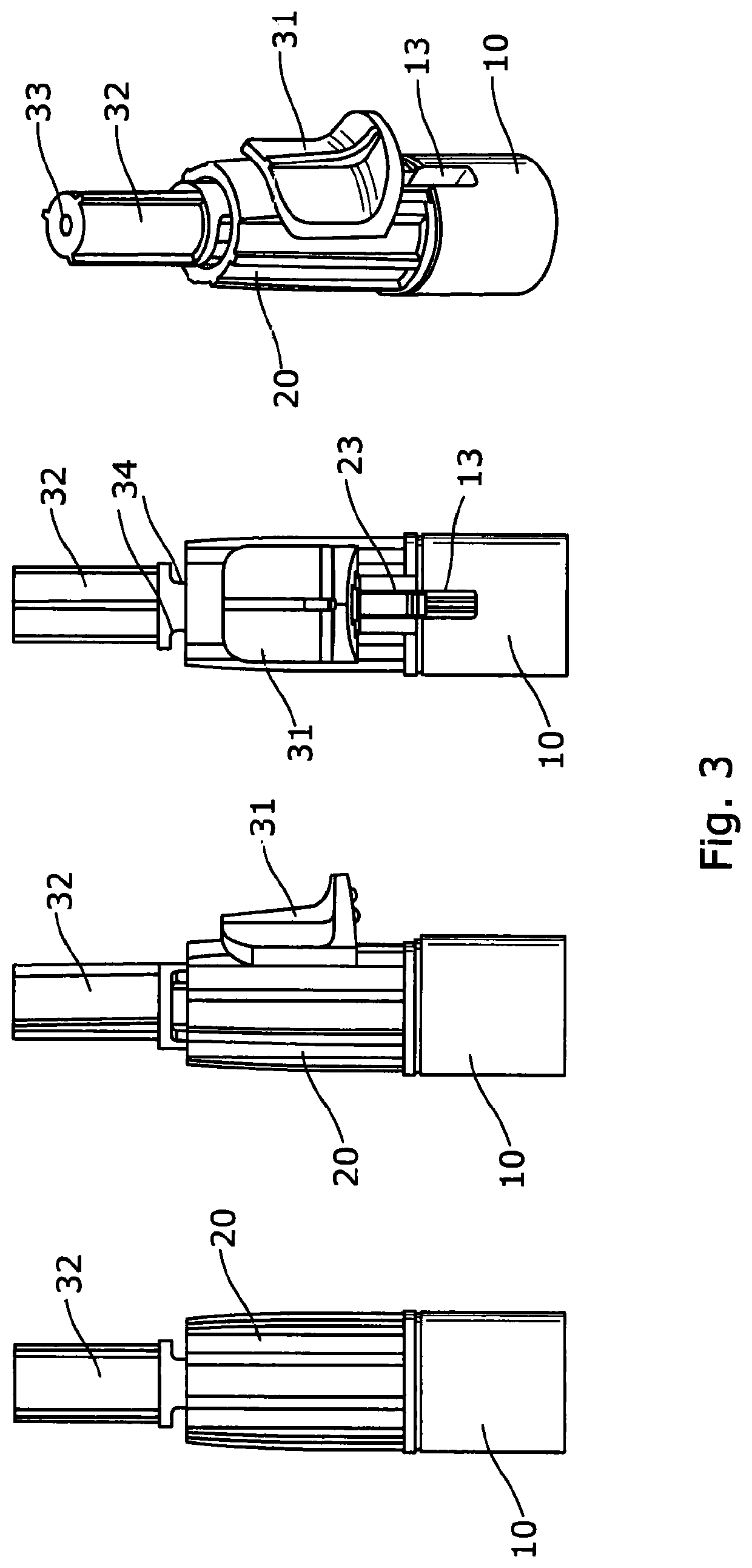
[0091]With particular reference to FIGS. 1 to 4, a needle assembly 1 in accordance with a first embodiment comprises a body, formed of a hub 10 and a forward housing 20, a shield 30, a needle 40 and a needle supporting member 50. Each of the components are generally concentrically arranged around the axis of the needle 40.

[0092]The hub 10 and forward housing 20 together define a main body of the needle assembly 1 having a generally cylindrical form. A snap fit engagement arrangement is provided between the hub 10 and forward housing 20 in the form of a recess 11 at the forward end of the hub 10 which receives a collar 21 at the rearward end of the forward housing 20.

[0093]The forward housing 20 has a generally annular profile with a bore 22 extending through the housing. An axial slot 13 / 23 is defined in the housing by a first slot portion 23 in the forward housing 20 and a second slot portion 13 in the hub 10. Two resilient members 24 are formed in the sides of the slot and are slo...

second embodiment

[0104]FIGS. 7A to 12B show a needle assembly 100 in accordance with The retractable needle assembly includes a body, formed of a forward housing portion 120 and a hub portion 110; a shield 130, a needle 140 and a needle supporting member 150. As with the earlier embodiment, each of these components is concentrically arranged around the axis A of the needle 140 (FIGS. 8A and 8B).

[0105]In this embodiment the forward housing portion 120 and the hub portion 110 are formed integrally to provide a body having a generally cylindrical form. The forward housing portion 120 has a generally annular shape with a bore 122. Two diametrically opposite projections 124 are provided at a front end of the forward housing portion 120, the projections extend out from the outer surface of the forward housing portion 120. The projections 124 have a sloped rear surface 124a, and a stepped forward surface 124b. The outer surface of the forward housing portion 120 is provided with an injection completion in...


PUM


Abstract

A needle assembly for mounting on an injection device which comprises a body configured to be attached to an injection device in use; a double ended needle; and a needle shield coupled to the body. The needle shield is arranged for axial movement with respect to the body. The needle assembly has an injection configuration, in which the shield is positioned such that the forward tip of the needle projects beyond a forward end of the shield. The needle assembly also has a shroud configuration, in which the shield is positioned such that the forward end of the shield extends beyond the forward tip of the needle. The needle assembly further comprises a needle support fixed relative to the body when the needle assembly is in the injection configuration. Movement of the shield from the injection configuration to the shroud configuration axially displaces the needle support relative to the body.

Description

CROSS-REFERENCE TO RELATED APPLICATIONS[0001]This application represents the U.S. National Stage of International Application No. PCT / GB2016 / 051334 filed May 10, 2016 which is incorporated by reference in its entirety and is based on, claims priority to, and incorporates herein by reference in their entireties, British Patent Application Serial Nos. GB 1507981.7, filed May 11, 2015, and GB 1518649.7, filed Oct. 21, 2015.FIELD OF THE INVENTION[0002]This invention relates to a needle assembly, and in particular, but not exclusively to a single-use disposable needle assembly. Such needle assemblies are typically configured for attachment to an injection device, cartridge or syringe.BACKGROUND OF THE INVENTION[0003]Injection devices, such as the Owen Mumford Autopen®, are commonly used by patients to self-administer injections of medicament. Such devices are typically provided in a pen-like body which contains, defines or receives a cartridge or syringe of medicament. The injection devi...

Claims


Application Information

Patent Timeline
Patent Type & Authority Patents(United States)
IPC IPC(8): A61M5/32
CPCA61M5/321A61M5/3245A61M5/3257A61M5/3213A61M5/3243A61M5/3202A61M2005/3254A61M5/32A61M5/3293A61M5/5086A61M5/002
Inventor CALVERT, JACK
Owner OWEN MUMFORD
Why Eureka
Try Eureka