
Methods and devices for analyte sensing in potential spaces

a potential space and analyte technology, applied in the field of continuous biochemical monitoring systems, can solve the problems of reducing the immune response of the device, unable to communicate with the device from outside the body, and insufficient closed loop system, etc., to achieve faster glucose sensing kinetics, faster insulin delivery, and the effect of reducing the risk of infection

Active Publication Date: 2020-04-07
THERANOVA LLC
View PDF38 Cites 1 Cited by
  • Summary
  • Abstract
  • Description
  • Claims
  • Application Information

AI Technical Summary

Benefits of technology

This approach offers 2-fold faster glucose sensing, reduced lag times, and improved accuracy and reliability for closed-loop glucose control, enabling more effective management of blood glucose levels with reduced immune response and longer implant life.

Problems solved by technology

Various, anatomical locations have been evaluated for blood glucose measurements, such as saliva and tears, and have been deemed inadequate for a closed, loop system due to latent lag times and interferences.
Positioning a sensor within a potential space, for example, within the peritoneal cavity, rather than subcutaneously, reduces the immune response to the device.
However, implanting a device more deeply within the body, and communicating with the device from outside the body can be challenging.

Method used


Image

  • Methods and devices for analyte sensing in potential spaces
  • Methods and devices for analyte sensing in potential spaces
  • Methods and devices for analyte sensing in potential spaces

Examples


Embodiment Construction

[0043]The peritoneal sensor system generally includes a sensor ‘sampler’ portion, which is implanted in the peritoneal space, and a control portion / controller, which may be implanted elsewhere, such as subcutaneously, or may be external to the patient. Other functions which may be included include insulin delivery, sensor flushing, wireless communication, light spectroscopy, UV sterilization, analyte sampling, analyte circulation, logic, etc.

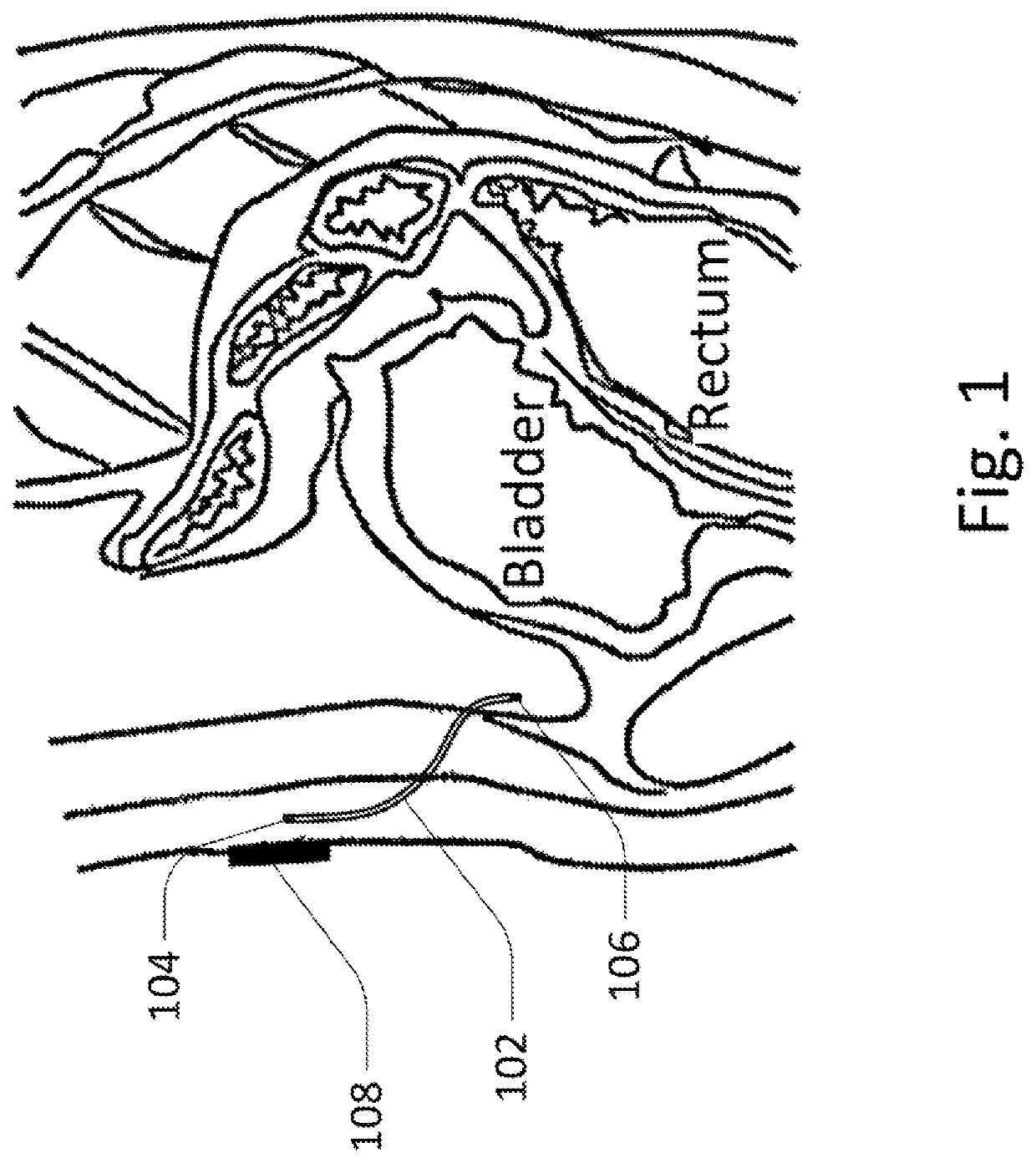
[0044]FIG. 1 shows an embodiment of the peritoneal sensor system with a tether / catheter which includes wireless communication. The embodiment of the peritoneal sensor system shown here includes catheter / tether 102 including subcutaneous antenna 104 on one end, and sensor portion 106 on the other end. For example, the sensor may sense the presence of glucose. This allows the sensor portion to communicate with external transmitting controller 108 where the sensor portion has low power requirements despite its position deep within the body. This de...


PUM


Abstract

Use of the peritoneal space provides a more direct tracking of blood glucose, capturing faster glucose kinetics, avoiding membrane / encapsulation effects, having less lag time and lag time variability, and eliminating the effect of variations in skin temperature, cardiac output, and body position during sleep. A peritoneal sensor system may be implanted within the peritoneal space and may generally include a sensor / sampler portion, which is implanted in the peritoneal space, and a control portion / controller, which may be implanted elsewhere, such as subcutaneously, or may be external to the patient.

Description

CROSS-REFERENCE TO RELATED APPLICATIONS[0001]This application is a continuation of International Application No. PCT / US20151065387 filed Dec. 11, 2015, which claims the benefit of priority to U.S. Provisional Application Nos. 62 / 098,950 filed Dec. 31, 2014 and U.S. Provisional Application No. 62 / 102,528 filed Jan. 12, 2015, each of which is incorporated herein by reference in its entirety.FIELD OF THE INVENTION[0002]The present invention relates to the field of continuous biochemical monitoring systems. More specifically, the present invention relates to continuous glucose measuring devices with minimal lag.INCORPORATION BY REFERENCE[0003]All publications and patent applications mentioned in this specification are herein incorporated by reference to the same extent as if each such individual publication or patent application were specifically and individually indicated to be so incorporated by reference.BACKGROUND OF THE INVENTION[0004]Diabetes is a group of diseases characterized b...

Claims


Application Information

Patent Timeline
Patent Type & Authority Patents(United States)
IPC IPC(8): A61M5/14A61B5/145A61B5/1459A61B5/00
CPCA61B5/0031A61B5/1459A61B5/6867A61B5/4839A61B5/14532A61B5/6852A61B5/14507A61B5/6874A61B5/6858
Inventor BURNETT, DANIEL R.LUXON, EVAN S.
Owner THERANOVA LLC
Learn More