Method and apparatus to improve lift to drag ratio of a rotor blade

a technology of rotor blade and lift to drag ratio, which is applied in the field of aircraft rotor blades, can solve the problems of undesirable removable fairing on or associated with the rotor blade, the root portion and the inability to efficiently handle the wide range of operating conditions, etc., and achieve the effect of improving the lift to drag ratio of the rotor blad

Active Publication Date: 2020-03-31
BELL HELICOPTER TEXTRON INC
View PDF20 Cites 2 Cited by
  • Summary
  • Abstract
  • Description
  • Claims
  • Application Information

AI Technical Summary

Benefits of technology

[0006]In a first aspect, there is provided a method for improving a lift to drag ratio of a rotor blade, including providing a blade member having a leading edge and a trailing edge; providing a leading edge extension member; and coupling the leading edge extension member to a portion of the leading edge of the blade member to form the rotor blade.
[0029]In a fourth aspect, there is provided a method for designing a rotor blade for generating improved lift and reduced drag as compared to a conventional rotor blade including increasing the chord length of the root portion of the rotor blade by disposing a leading edge extension member on the leading edge of a blade member.
[0030]In a fifth aspect, there is provided a method for increasing the chord length C2 in a root portion of a rotor blade by coupling a leading edge extension member having a hollow interior portion to a leading edge of a blade member.
[0031]In a sixth aspect, there is provided a method of improving the lift to drag ratio of a rotor blade including providing a blade member having a root portion, a tip portion, a leading edge, and a trailing edge, providing a leading edge extension member having a hollow interior portion for receiving the blade member; selectively tailoring the leading edge extension member to determine the lift to drag ratio of a rotor blade; coupling the leading edge extension member to the root portion of the blade member to form the rotor blade.

Problems solved by technology

The profile of the root portion of the rotor blade with a large thickness t to chord C ratio, see FIG. 4A, cannot efficiently handle the wide range of operating conditions that the blade experiences due to early chordwise separation and subsequent rise in profile drag.
Additionally, a removable fairing on or associated with a rotor blade is undesirable as the removable fairing can add weight to the blade and decrease efficiency during operation of the aircraft.

Method used


Image

  • Method and apparatus to improve lift to drag ratio of a rotor blade
  • Method and apparatus to improve lift to drag ratio of a rotor blade
  • Method and apparatus to improve lift to drag ratio of a rotor blade

Examples


Embodiment Construction

[0052]Illustrative embodiments of the apparatuses and methods to improve lift to drag ratio of a rotor blade are described below. In the interest of clarity, all features of an actual implementation may not be described in this specification. It will of course be appreciated that in the development of any such actual embodiment, numerous implementation-specific decisions must be made to achieve the developer's specific goals, such as compliance with system-related and business-related constraints, which will vary from one implementation to another. Moreover, it will be appreciated that such a development effort might be complex and time-consuming but would nevertheless be a routine undertaking for those of ordinary skill in the art having the benefit of this disclosure.

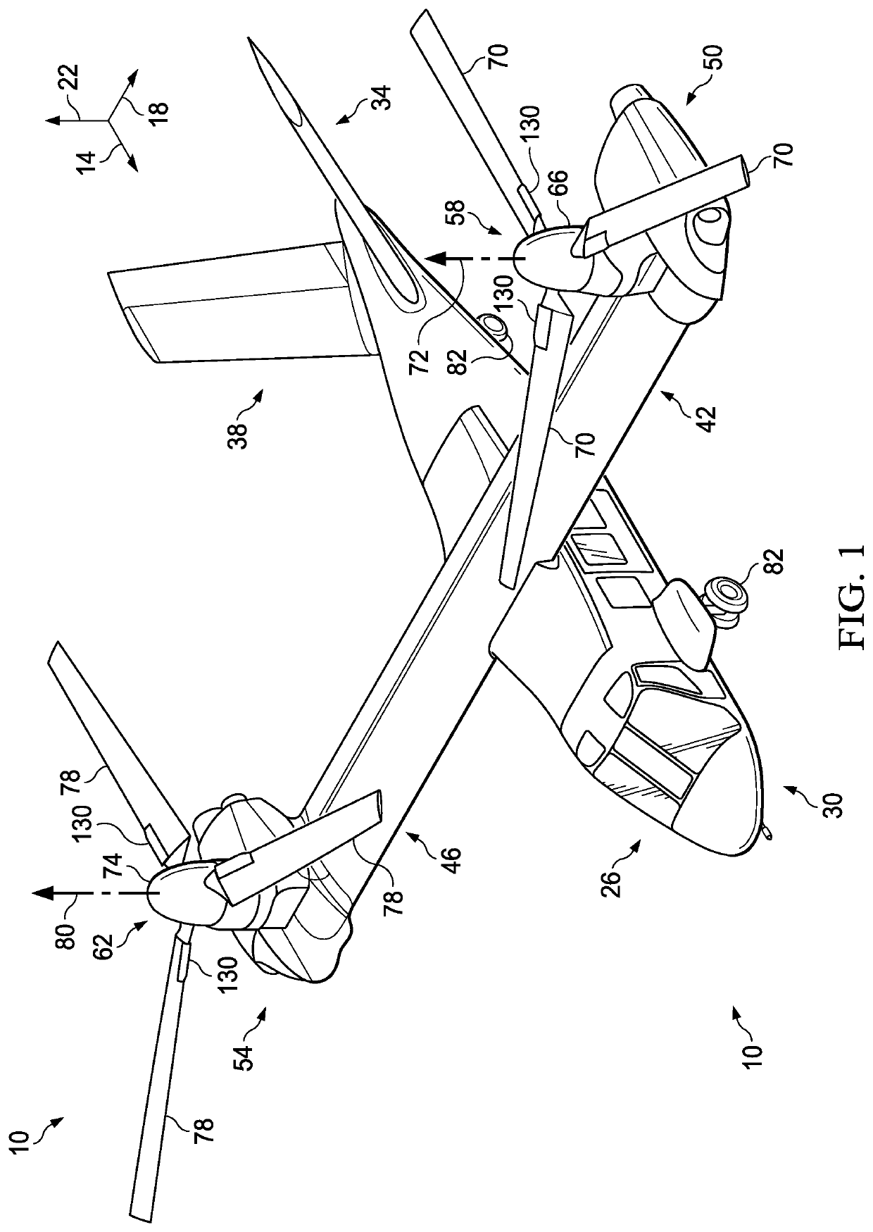
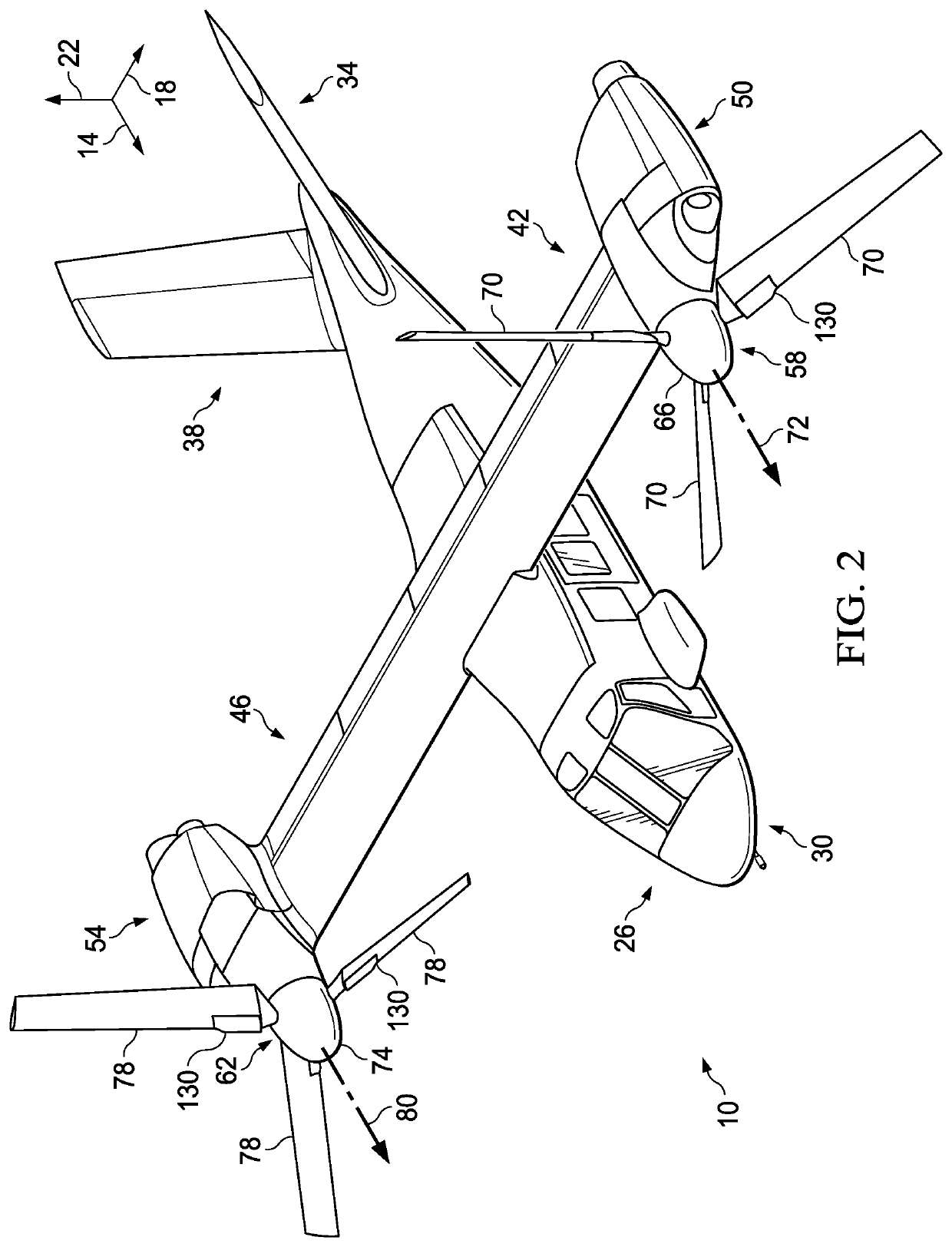
[0053]In the specification, reference may be made to the spatial relationships between various components and to the spatial orientation of various aspects of components as the devices are depicted in the attached dra...


PUM


Abstract

In a first aspect, there is a method for improving a lift to drag ratio of a rotor blade, including providing a blade member having a leading edge and a trailing edge; providing a leading edge extension member; and coupling the leading edge extension member to a portion of the leading edge of the blade member to form the rotor blade. In a second aspect, there is a rotor blade including a blade member having a leading edge, and a trailing edge; and a leading edge extension member disposed on the leading edge of the blade member, wherein the leading edge extension member is configured to extend the chord length of at least a portion of the rotor blade. In a third aspect, there is a leading edge extension member for a rotor blade including a convex exterior surface configured to extend at least a portion of the chord length of the rotor blade.

Description

CROSS-REFERENCE TO RELATED APPLICATION[0001]This application claims priority to U.S. provisional patent application No. 62 / 521,393, filed Jun. 17, 2017, all of which is hereby incorporated by reference for all purposes as if fully set forth herein.BACKGROUNDTechnical Field[0002]The present disclosure relates to aircrafts and, more particularly, to aircraft rotor blades.Description of Related Art[0003]The root portion of a rotor blade for a vertical take-off and landing (VTOL) aircraft experiences a wide range of aerodynamic conditions from hover (low relative velocity, high angle of attack) to cruise (high relative velocity, zero angle of attack). The conventional profile of the root portion of the rotor blade is typically thicker than the tip portion to accommodate hub attachment, bearings, and clearance through a large feathering motion range. The profile of the root portion of the rotor blade with a large thickness t to chord C ratio, see FIG. 4A, cannot efficiently handle the wi...

Claims


Application Information

Patent Timeline
Patent Type & Authority Patents(United States)
IPC IPC(8): B64C11/18B64C11/24B64C27/473F03D1/06B64C29/00
CPCF03D1/0683B64C11/18B64C27/473B64C11/24B64C29/0033Y02E10/72F03D1/0675
Inventor FOSKEY, CHRISTOPHER E.LANIGAN, BRENDAN P.
Owner BELL HELICOPTER TEXTRON INC
Why Eureka
Try Eureka