
2D-3D sculpture paintings

a sculpture and 3d technology, applied in the field of high relief and basrelief synthesis, can solve the problems of difficult to distinguish between the 2d and the 3d parts, cannot generate plausible reliefs for higher depth range variations, and the difficulty of creating a composition that provides plausible percepts for many different viewing angles

Active Publication Date: 2020-03-17
ECOLE POLYTECHNIQUE FEDERALE DE LAUSANNE (EPFL)
View PDF2 Cites 0 Cited by
  • Summary
  • Abstract
  • Description
  • Claims
  • Application Information

AI Technical Summary

Benefits of technology

[0016](v) adding bas-relief profiles to the non-ROI part of the salient object and ensuring smoothness between flat, bas-relief and 3D object parts by an optimization procedure with the additional constraint that the silhouette of the non-ROI part of the object remains close to the rendering grid.
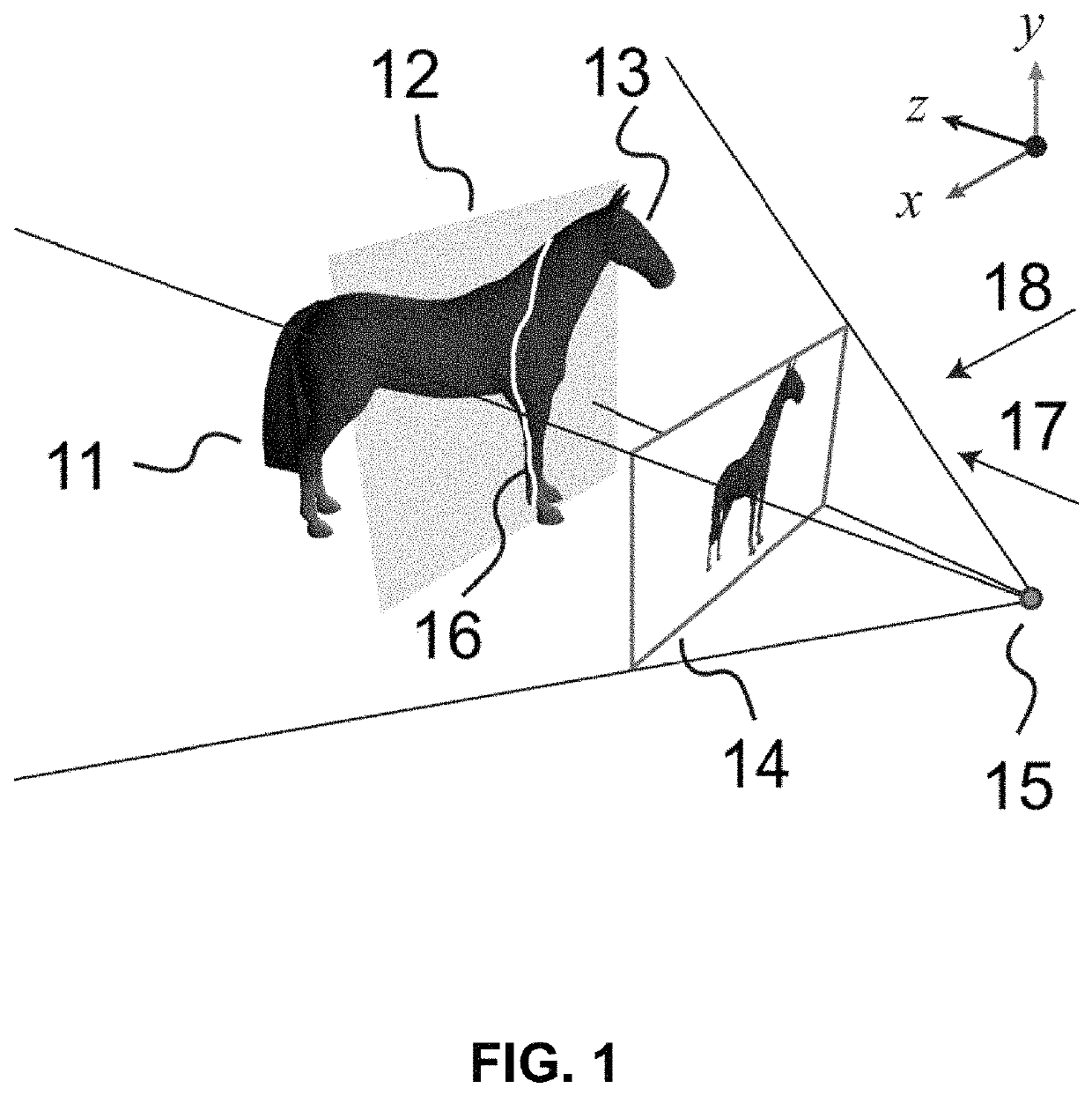
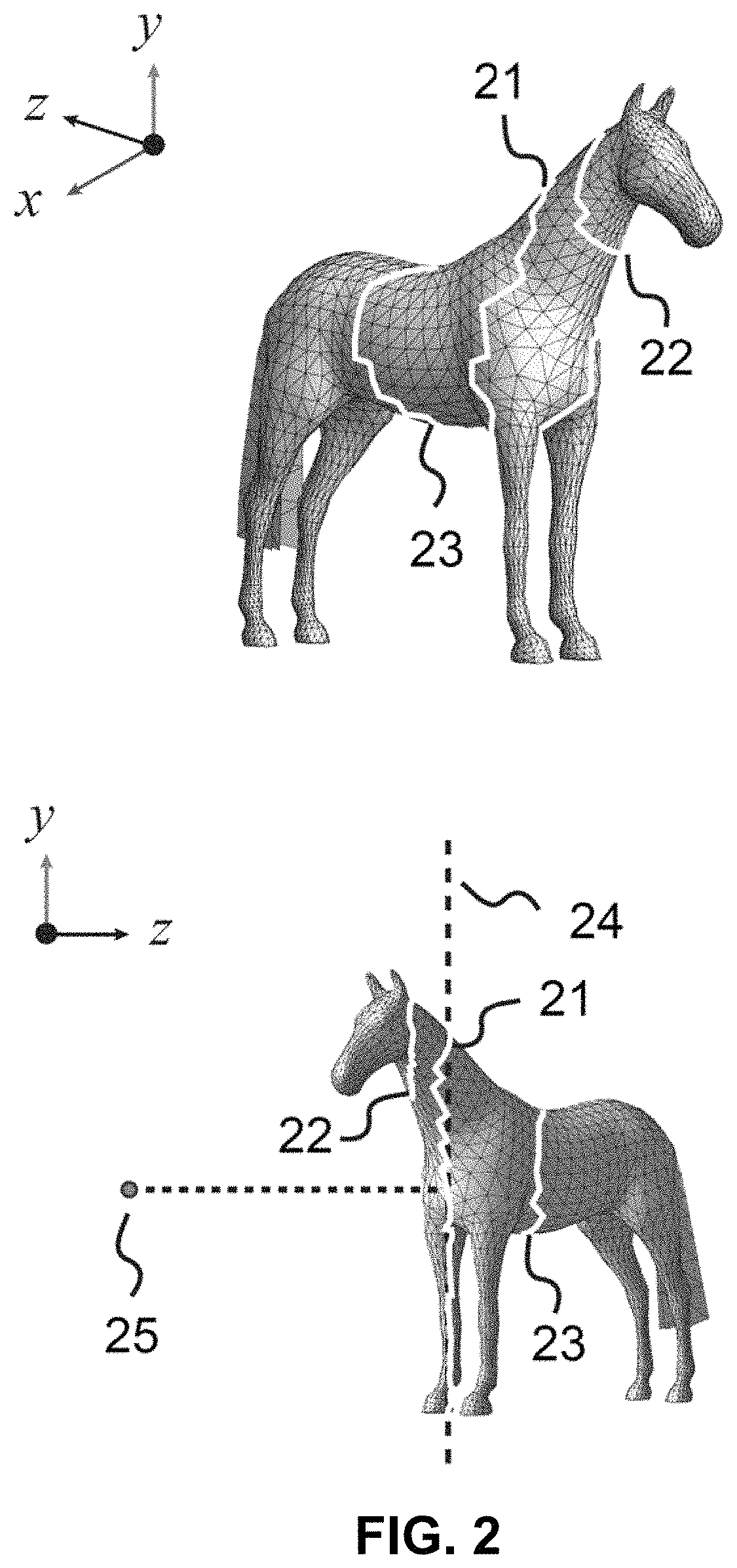
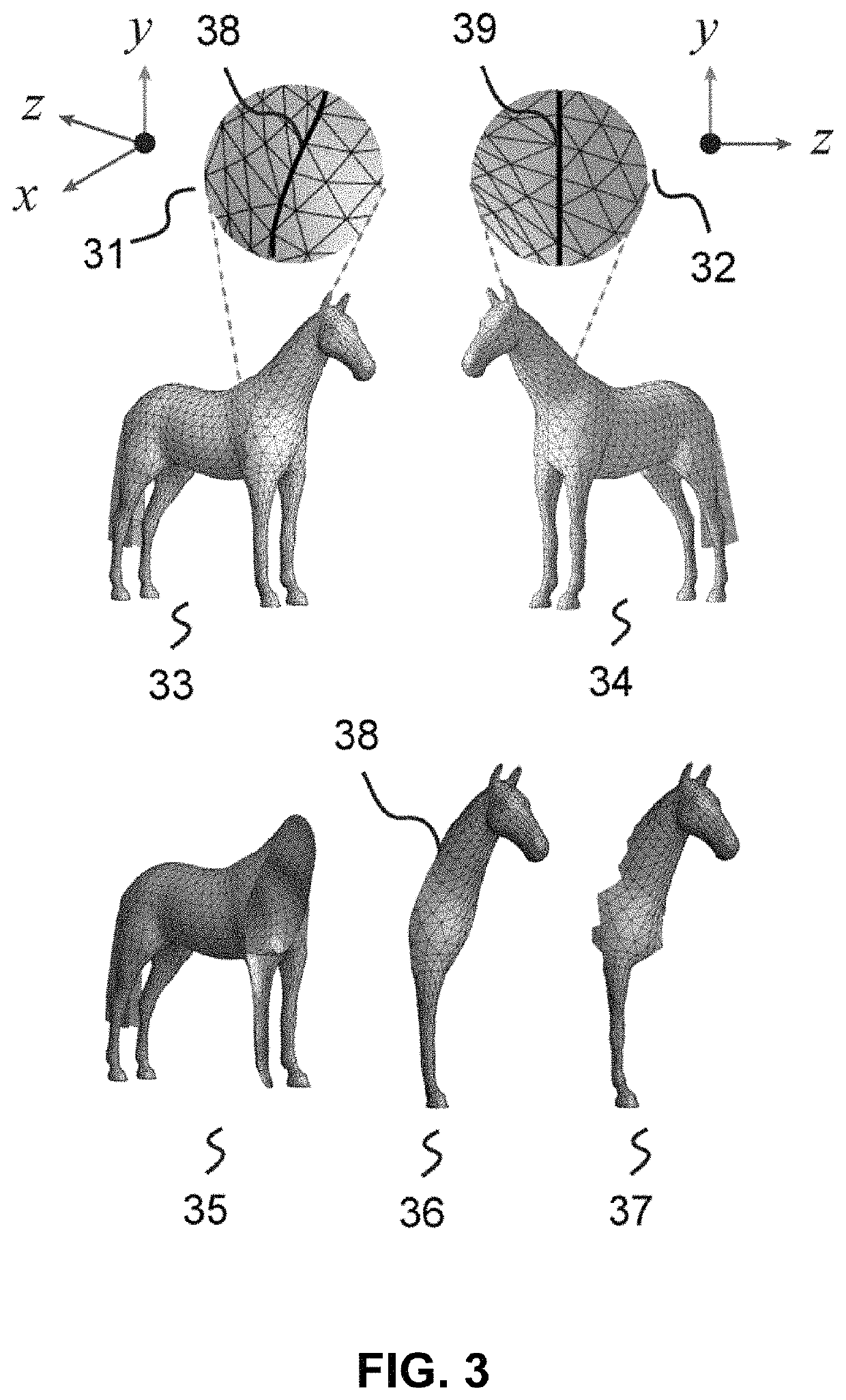
[0017]The surface of the salient object within the original scene is formed by a mesh whose vertices and edges are well defined. Aligning and smoothing the boundary along the cut plane is carried out by forcing boundary vertices to be located close to the cut plane and by refining the location of mesh vertices with an optimization procedure that minimizes differences between original differential coordinates of the mesh vertices and differential coordinates of the refined mesh vertices.
[0018]The non-ROI part of the salient object is attached to the rendering plane by forcing its silhouette to remain on the rendering plane or very close to it. This is performed by applying an optimization procedure that keeps the elevation from the rendering plane of the silhouette vertices of that salient object very small and that also minimizes differences between original differential coordinates of the mesh vertices and differential coordinates of the refined mesh vertices. Silhouette vertices are those which have a high gradient of their depth profile.
[0024]The 2D-3D artworks create plausible effects for the viewers by showing a different relationship between 2D and 3D at each viewing angle. As the viewing angle is changed, an observer can see 3D elements emerging from the scene, but without being able to sharply locate the boundary between flat parts, low elevation parts and parts emerging as 3D. This yields a very interesting aesthetical effect.
[0025]The invented method can be used to reproduce several 2D-3D objects within a scene by applying the method object by object. The method can also be easily extended by persons knowledgeable in the art to handle composite objects made of several parts, such as a horse carrying a carriage or a two headed hydra whose heads are represented as 3D object parts.

Problems solved by technology

An observer looking at the final printed 2D-3D artwork resulting from such a composition cannot easily distinguish the 2D part and the 3D part.
The main challenge of the bas-relief methods consists in mapping the height-field of the scene to a limited range of elevations while preserving the details of the original scene.
However, they cannot generate plausible reliefs for higher depth range variations.
Creating a composition that provides plausible percepts for many different viewing angles is challenging.
This makes it difficult for an observer looking at the piece of art from various angles to perceive the exact position of the transitions between the flat, the bas-relief and the 3D parts of the object.

Method used


Image

  • 2D-3D sculpture paintings
  • 2D-3D sculpture paintings
  • 2D-3D sculpture paintings

Examples


Embodiment Construction

[0037]We propose a synthesis method where parts of a given 3D scene are rendered on a substantially planar surface (“rendering plane”) and user selected parts emerge as 3D shapes from the rendering surface. The final geometry is a fully connected mesh where 2D parts and 3D parts are within the same continuum. In order to provide an improved means of user interaction, we define two separate planes: a rendering plane that is the base plane (or background plane) for representing the final composition and a cut plane which provides user control over the selection of the region of interest (“ROI”) of an object within the scene. This region of interest is to be reproduced in 3D. The proposed method and system aim at creating a seamless continuity between the 2D and the 3D parts of an object surface, allowing the user to perceive from a variety of viewing positions plausible compositions comprising 3D elements emerging from the rendering plane.

[0038]The initial challenge consists of matchi...


PUM


Abstract

We disclose a method for synthesizing by computer an artwork where 2D and 3D contents are integrated within a same composition. Such an artwork creates plausible effects for the viewers by showing a different relationship between 2D and 3D at each viewing angle. Methods are proposed for ensuring the continuity between the 2D and the 3D parts in terms of mesh geometry and reflected colors. The user selects from a given scene a region of interest (ROI) to be reproduced in 3D. A flat rendering grid is created that matches the topology and tesselation of the ROI. The ROI is attached to the rendering grid. To enhance the continuity between the 2D and the 3D parts of a scene object, the 2D part of the object can be represented as bas-relief. Designers can create 2D-3D sculpture paintings for decoration, exhibitions, and homes.

Description

BACKGROUND OF THE INVENTION[0001]The present invention is related to the field of partially or fully automatic synthesis of art pieces by computer executed methods such as the synthesis of digital reliefs, the synthesis of sculptures, and, more specifically, to methods for the synthesis of bas-reliefs and of high reliefs.[0002]In the present disclosure, non-patent publications are cited by a number, e.g. [1], which refers to the publications listed in section “Cited non-Patent Publications” at the end of the description.[0003]We disclose a system for generating by computer pieces of art that are partly sculpture and partly image, incorporating visually smooth transitions between 3D scene objects and their flat representations. We provide new means of expression combining within a same composition 2D and 3D scene elements. An observer looking at the final printed 2D-3D artwork resulting from such a composition cannot easily distinguish the 2D part and the 3D part.[0004]Automatic gene...

Claims


Application Information

Patent Timeline
Patent Type & Authority Patents(United States)
IPC IPC(8): G06T19/20G06T11/80G06T17/20G06T11/60
CPCG06T19/20G06T17/20G06T11/60G06T11/80
Inventor ARPA, SAMISÜSSTRUNK, SABINEHERSCH, ROGER D.
Owner ECOLE POLYTECHNIQUE FEDERALE DE LAUSANNE (EPFL)
Learn More