
Piling construction management method

a construction management and construction technology, applied in the direction of construction, force/torque/work measurement apparatus, instruments, etc., can solve the problems of large amount of labor, time and cost, large amount of digging load, and significant increase of digging load, so as to achieve easy and swift connection and easy response

Active Publication Date: 2020-02-11
OAK SA
View PDF16 Cites 0 Cited by
  • Summary
  • Abstract
  • Description
  • Claims
  • Application Information

AI Technical Summary

Benefits of technology

The present invention provides a method for managing piling construction to prevent insufficient support strength. This method allows for easy and reliable determination of whether or not a support force is sufficient for a cast-in-place piling or a precast piling before it is placed in a piling hole. This helps to avoid the need for additional work to fix any issues with the piling construction.

Problems solved by technology

Generally, whether or not a piling support force after completion of erection by these construction methods is sufficient can be determined by a load carrying test, however, when insufficient support strength is found by this test, large amounts of labor, time, and cost are needed for redoing piling construction, it is therefore ideal if it can be determined whether or not a support force of a dug piling hole is sufficient for a pile distal end before erecting the piling.
However, in the method in which a change in digging load is detected from a current value of a rotary drive motor, as a dug hole becomes deeper, as frictional resistance between the digging member and the hole wall increases, the digging load significantly increases even when the hole does not reach a bearing stratum, and to the contrary, due to slippage occurring at a digging portion, the digging load decreases although the hole has reached a bearing stratum, and further, the digging load greatly fluctuates depending on an operator's digging operation skill, therefore, the change in digging load is poor in reliability as an index of confirmation of reach to a bearing stratum.
Therefore, generally, exclusively based on data of a geological sample obtained through pilot boring at a planned construction site, digging to a prescribed depth is usually regarded as reaching a bearing stratum, however, the deep underground of the entire planned construction site is not always uniform in stratigraphic succession and homogeneous, and depending on geological history, there are many cases where the depth of the bearing stratum locally differs or the hardness of the bearing stratum greatly differs, therefore, it cannot be said that bottom portions of individual piling holes do not have sufficient support forces for piling distal ends in actuality.

Method used


Image

  • Piling construction management method
  • Piling construction management method
  • Piling construction management method

Examples


first embodiment

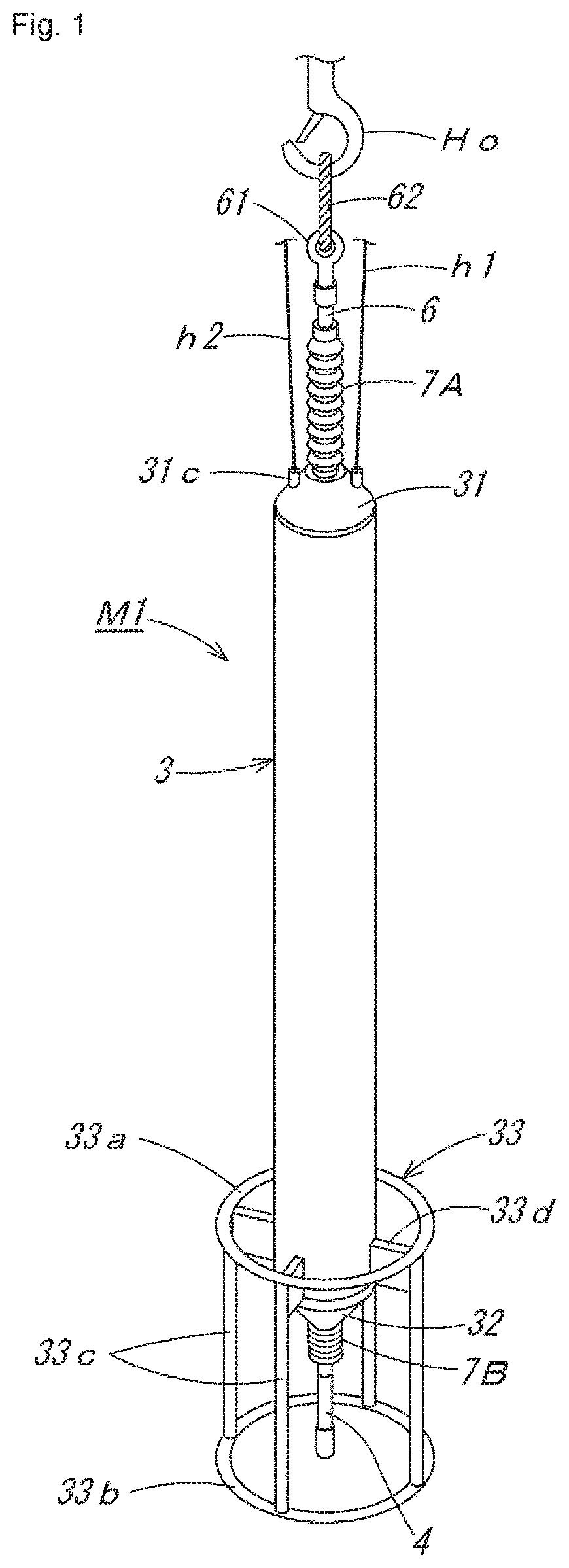
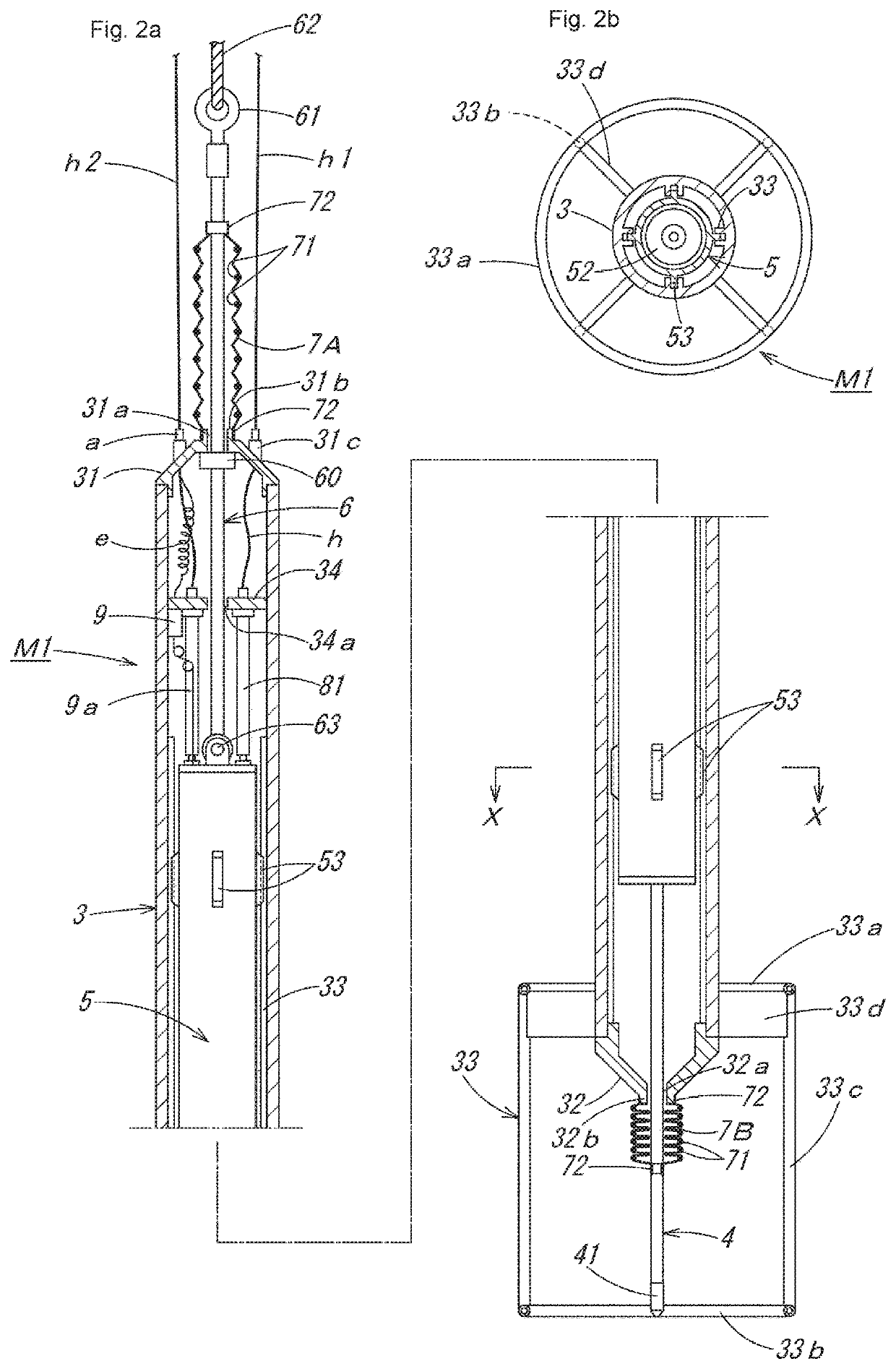
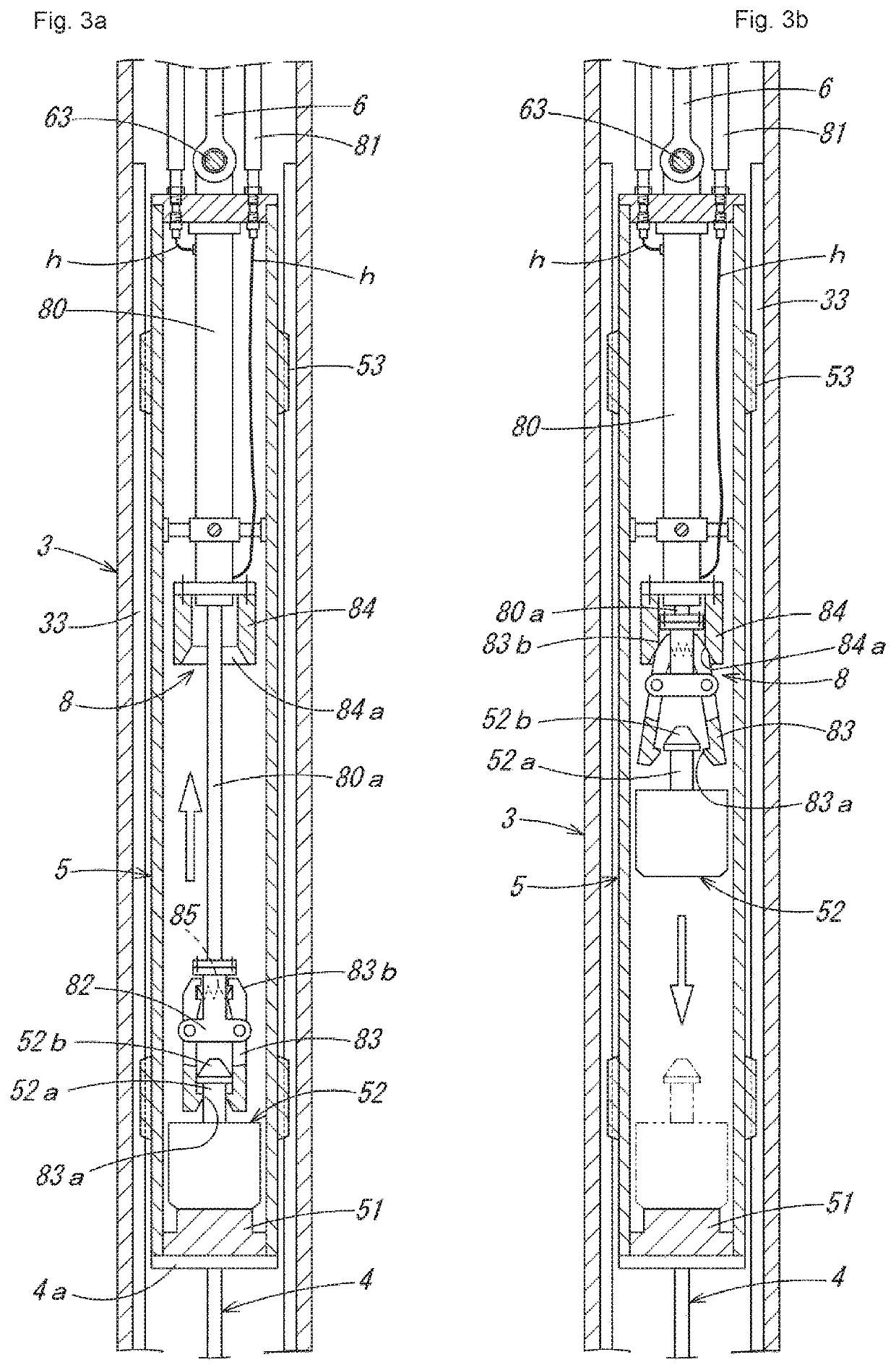
[0057]As a piling construction management method using the penetration testing device M1 of the suspended type described above, first, piling construction of a first embodiment by a preboring method is described in order of steps shown in FIG. 5 and FIG. 6. In this piling construction, FIG. 5(a): a screw rod Rs is attached to an auger machine A that moves up and down along a leader (not shown in the drawing) of a three-point pile driver, etc., and the screw rod Rs is lowered while being driven to rotate to dig the ground G, and FIG. 5(b): after a piling hole H1 with a depth reaching an estimated bearing stratum Gh of deep underground is formed, FIG. 5(c): while the screw rod Rs is pulled up, a foot protection liquid Ls such as soil cement is injected, and FIG. 5(d): subsequently, a hole circumference fixative solution Lf is injected up to an upper portion of the piling hole H, the screw rod Rs is pulled out, and then FIG. 5(e): the penetration testing device M1 suspended by a wire W...

second embodiment

[0063]Next, as a piling construction management method using the penetration testing device M1 of the suspended type described above, piling construction of a second embodiment by a kelly bar type earth drilling method is described in order of steps shown in FIG. 8 and FIG. 9. In this piling construction, FIG. 8(a): a weak stratum Gs at an upper level of the ground is dug and soil is removed by a shaft digging bucket B1 connected to a kelly bar K of an earth drill machine, FIG. 8(b): a standpipe Ps is press-fitted into the dug hole, FIG. 8(c): while injecting a slurry Ls such as a bentonite solution into the hole, digging and soil removal are performed by a replaced shaft digging bucket B2 with a small diameter, and accordingly, FIG. 8(d): a piling hole H1 with a depth reaching an estimated hard bearing stratum Gh of deep underground is formed. Then, FIG. 8(e): inside the piling hole H1 from which the shaft digging bucket B2 has been pulled out, a penetration testing device M1 suspe...

third embodiment

[0066]Next, as a piling construction management method using the penetration testing device M1 of the suspended type described above, piling construction of a third embodiment by an all casing method is described in order of steps shown in FIG. 10 and FIG. 11. In this piling construction, FIG. 10(a): a tubing machine TM is disposed on the ground at a boring position, a steel-made casing tube CT suspended by a wire W of a crane is set in the tubing machine TM, FIG. 10(b): while the casing tube CT is pressed into the ground while being swung and / or rotated all around, the inside of the casing tube CT is dug and soil is removed by a hammer grab HG, FIG. 10(c): by adding casing tubes CT and continuing digging and soil removal, a piling hole H1 with a depth reaching an estimated bearing stratum Gh of deep underground is formed, and after hole bottom treatment is performed with the hammer grab HG or a sedimentation bucket (not shown in the drawing), FIG. 10(d): the penetration testing dev...


PUM

PropertyMeasurementUnit
inner diameteraaaaaaaaaa

Abstract

In a piling construction management method a support strength of a hole bottom is measured with a penetration testing device before erecting a piling in a piling hole. The piling is erected in the piling hole when the measurement is at least a prescribed value. The penetration testing device has a knocking block with an integrated penetration shaft and the block is struck by a drive hammer in free-fall. The penetration testing device determines the support strength from the number of impacts required for the penetration shaft to penetrate to a prescribed depth from the hole bottom.

Description

TECHNICAL FIELD[0001]The present invention relates to a piling construction management method to erect a precast piling or cast-in-place piling in a piling hole bored in the ground by a preboring method, an earth drilling method, and an all casing method, etc.BACKGROUND ART[0002]Conventionally, in construction of a precast piling by a preboring method, generally, by lowering a screw rod attached to an auger machine that moves up and down along a leader of a three-point pile driver, etc., while driving and rotating the screw rod, the ground is dug and a piling hole is formed to have a depth reaching an estimated bearing stratum of deep underground, and thereafter, while the screw rod is pulled up, a foot protection liquid such as soil cement is injected into the piling hole, and subsequently, a hole circumference fixative solution is injected up to an upper portion of the piling hole, and this screw rod is pulled out, and then a precast piling such as a PHC piling or PRC piling is co...

Claims


Application Information

Patent Timeline
Patent Type & Authority Patents(United States)
IPC IPC(8): E02D1/02E02D5/34E02D5/24E02D13/06G01L5/00E02D1/00E02D7/10
CPCG01L5/0052E02D1/02E02D7/10E02D5/34E02D5/24E02D13/06E02D1/022
Inventor KASHIMOTO, TAKAHIKO
Owner OAK SA
Learn More