Hydrostatic transmission assembly and system

a transmission assembly and hydrostatic technology, applied in the direction of gearing control, gearing elements, gearing hoses, etc., can solve the problems of reducing machine reliability, increasing machine downtime, and complicated use of hoses, pipes and/or fittings

Active Publication Date: 2020-01-28
PROJECT PHOENIX
View PDF185 Cites 2 Cited by
  • Summary
  • Abstract
  • Description
  • Claims
  • Application Information

AI Technical Summary

Benefits of technology

[0006]Preferred embodiments of hydrostatic transmissions and power generating and transmitting methodologies provide for a compact and reliable design of a hydrostatic transmission. The preferred hydrostatic transmissions include a transmission casing, a hydraulic motor, a storage device, valves (e.g., isolation or lock valves) and a hydraulic pump. The hydraulic motor, the storage device, valves, and the hydraulic pump are disposed in the transmission casing and form a closed-loop hydraulic system. The hydraulic motor is driven by pressurized fluid transferred by the hydraulic pump. The hydraulic motor includes a motor casing that is conjoined with the transmission casing. The motor casing has a motor inlet and a motor outlet. Pressurized fluid enters the hydraulic motor through one of the ports, and exits the hydraulic motor through the other port during operation of the hydraulic motor. The storage device stores or releases pressurized fluid into the system as required. The hydraulic pump includes a pump casing that has two ports for the pump inlet and outlet depending on the direction of the pump, and a pair of fluid drivers. Each of the pair of drivers is supported on a respective shaft in an internal volume defined by the pump casing. Each of the pair of drivers is rotatably driven independently of the other and in an opposite direction with respect to the other. The ports of the pump are in fluid communication with respective ports on the hydraulic motor. In some embodiments, the storage device is in fluid communication with a port of pump via a through-passage through one of the shafts of the pump. One end of the through-passage defines an aperture for fluid communication with one of the inlet and the outlet of the casing, and the other end of the through-passage defines a port for fluid communication with the storage device. Of course, the transmission casing need not be a separate element and the motor casing and pump casing can be combined to form all or part of the transmission casing.
[0007]Exemplary embodiments are directed to hydrostatic transmission assembly and system and control methodologies that provides for precise control of the fluid flow and / or pressure in the system by using a variable-speed and / or a variable-torque pump. The hydrostatic transmission assembly and system and method of control thereof discussed below are particularly advantageous in a closed-loop type system since system and method of control provides for a more compact configuration without increasing the risk of pump cavitation or high fluid temperatures as in conventional systems. In an exemplary embodiment, a hydraulic system includes an integrated hydrostatic transmission assembly that controls a load. The integrated hydrostatic transmission assembly includes a hydraulic pump assembly having a hydraulic pump and two valve assemblies to provide hydraulic fluid to a hydraulic motor to operate the load, e.g., tractor wheel, excavator or some other rotatably driven device. The hydraulic system further includes a means for adjusting at least one of a flow and a pressure in the system to an operational set point. The adjustment means exclusively uses the hydraulic pump to adjust the flow and / or the pressure in the system, i.e., without the aid of another flow control device, to control the flow and / or pressure in the system to the operational set point.

Problems solved by technology

To interconnect these parts, various additional components like connecting shafts, hoses, pipes, and / or fittings are used in a complicated manner.
Moreover, these components are susceptible to damage or degradation, particularly in a harsh working environment, and thereby can cause increased machine downtime and reduce reliability of the machine.
However, these hydraulic systems can be relatively large and complex.
To interconnect these parts, various additional components like connecting shafts, hoses, pipes, and / or fittings are used in a complicated manner.
Moreover, these components are susceptible to damage or degradation in harsh working environments, thereby causing increased machine downtime and reduced reliability of the machine.

Method used


Image

  • Hydrostatic transmission assembly and system
  • Hydrostatic transmission assembly and system
  • Hydrostatic transmission assembly and system

Examples


Embodiment Construction

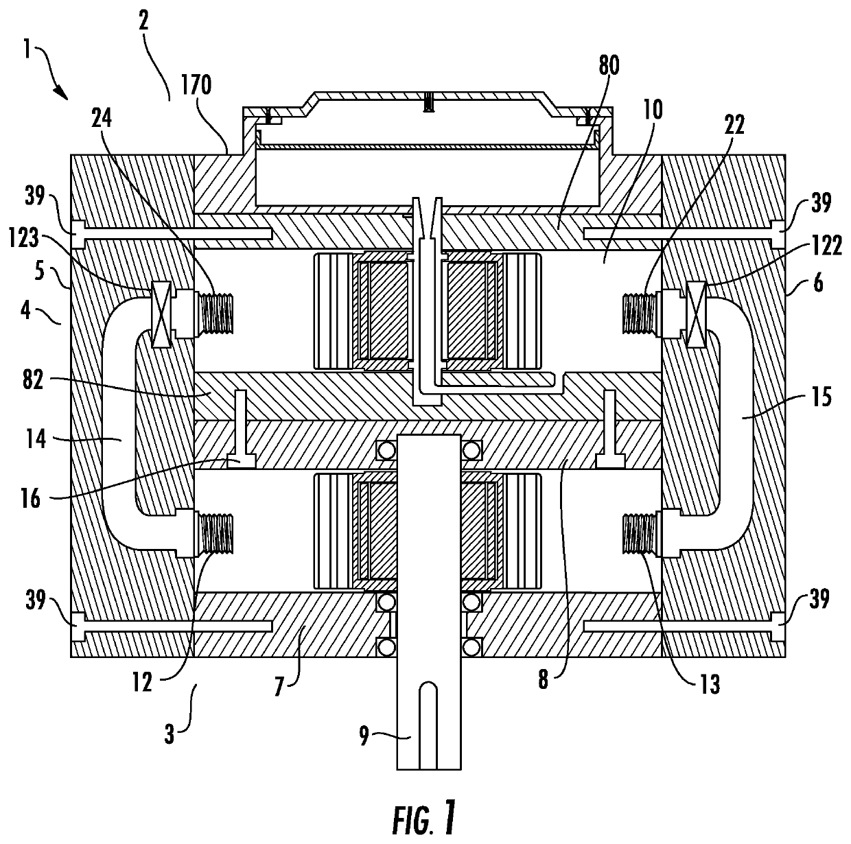
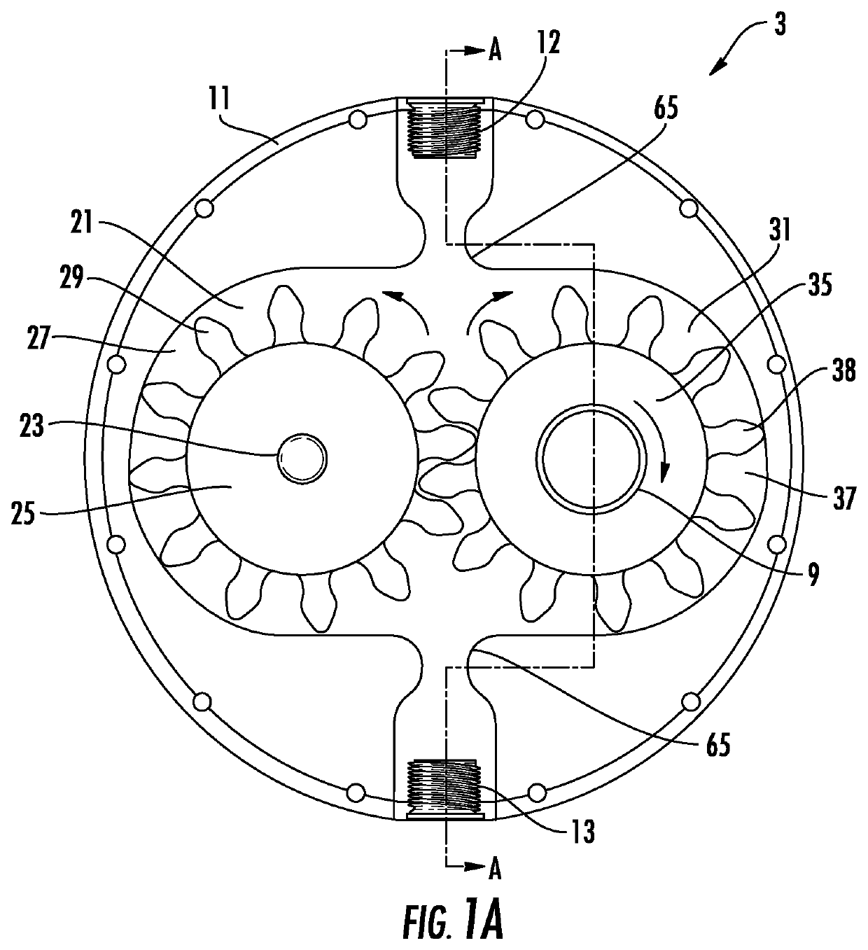
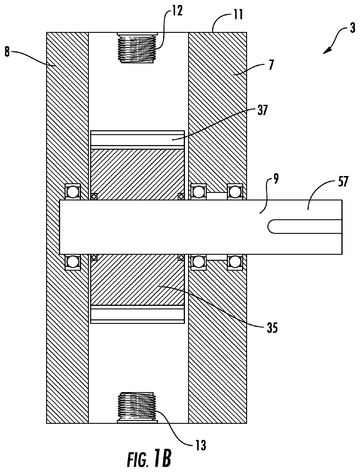
[0036]Exemplary embodiments of the present invention are directed to a hydrostatic transmission assembly and system with a fluid-driven motor and an integrated pump assembly conjoined with the fluid-driven motor to provide fluid to operate the fluid-driven motor. “Conjoined with” means that the devices are fixedly connected or attached so as to form one integrated unit or module. The integrated pump assembly includes a pump with at least one fluid driver comprising a prime mover and a fluid displacement assembly to be driven by the prime mover such that fluid is transferred from a first port of the pump to a second port of the pump. The pump assembly also includes two valve assembles to isolate the pump from the fluid system. In some embodiments the valve assemblies may be disposed separately from the pump assembly, e.g., as part of the fluid-driven motor. The fluid system also includes a controller that establishes at least one of a speed and a torque of the at least one prime move...


PUM


Abstract

A hydrostatic transmission system includes a fluid-driven motor and an integrated pump assembly connected to the fluid-driven motor to provide fluid to operate the fluid-driven motor. The integrated pump assembly includes a pump with at least one fluid driver comprising a prime mover and a fluid displacement assembly to be driven by the prime mover such that fluid is transferred from a first port of the pump to a second port of the pump. The pump assembly also includes two valve assembles to isolate the pump from the system. The hydrostatic transmission system also includes a controller that establishes at least one of a speed and a torque of the at least one prime mover to exclusively adjust at least one of a flow and a pressure in the hydrostatic transmission system to an operational set point.

Description

PRIORITY[0001]The present application claims priority to International Patent Application No. PCT / US15 / 33764 filed Jun. 2, 2015, which claims priority to U.S. Provisional Patent Application Nos. 62 / 006,760 filed on Jun. 2, 2014; 62 / 017,382 and 62 / 017,362 filed on Jun. 26, 2014; 62 / 031,560, 62 / 031,353, and 62 / 031,597 filed on Jul. 31, 2014; 62 / 054,176 filed on Sep. 23, 2014; 62 / 060,441 filed on Oct. 6, 2014, 62 / 066,238, 62 / 066,247, and 62 / 066,255 filed on Oct. 20, 2014, which are incorporated herein by reference in their entirety.TECHNICAL FIELD[0002]The present invention relates generally to hydrostatic transmissions and power generating and transmitting methodologies thereof. More particularly, the present invention relates to hydrostatic transmissions and control methodologies thereof in a fluid pumping or delivery system, including adjusting at least one of a flow and a pressure in the system using the at least one pump assembly and without the aid of another flow control device....

Claims


Application Information

Patent Timeline
Patent Type & Authority Patents(United States)
IPC IPC(8): F16H61/47F16H61/468F16H61/4061F16H39/36F16H61/4008F16H61/4035
CPCF16H61/4008F16H39/36F16H61/4035F16H61/47F16H61/468F16H61/4061F16H39/06F16H61/465
Inventor AFSHARI, THOMAS
Owner PROJECT PHOENIX
Why Eureka
Try Eureka