Hydraulic system

A hydraulic system and pump system technology, applied in the field of hydraulic systems, can solve the problems of hydraulic systems such as unreliability, failure-prone, and expensive, and achieve cost-effectiveness, reduce pump drive torque, and save energy.

Active Publication Date: 2022-03-04
NANJING BANGQI AUTOMATIC TRANSMISSION CO LTD
View PDF5 Cites 0 Cited by
  • Summary
  • Abstract
  • Description
  • Claims
  • Application Information

AI Technical Summary

Problems solved by technology

However, these multiple valves make the system rather complex, expensive and relatively bulky
Also, these valves can be easily damaged and prone to failure, making hydraulic systems relatively unreliable

Method used


Image

  • Hydraulic system
  • Hydraulic system
  • Hydraulic system

Examples


Embodiment Construction

[0035] In the drawings, the drawings are only given as schematic illustrations of the invention. Corresponding elements are indicated with corresponding reference numerals.

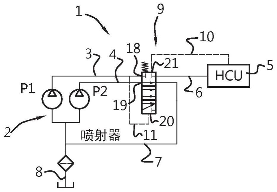
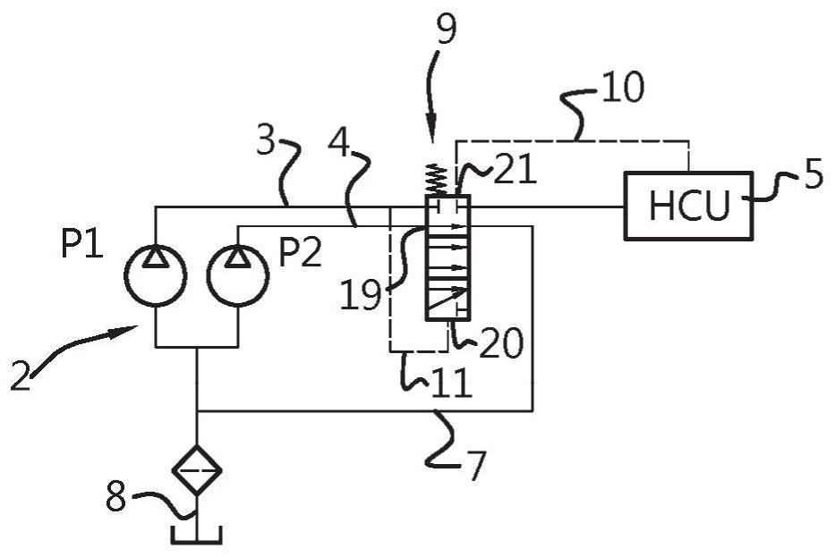
[0036] Figure 1A A part of a hydraulic diagram of a hydraulic system 1 for a vehicle transmission is shown. The hydraulic system 1 comprises a pump system 2 comprising two pumps or pump chambers P1 and P2 with at least two outlet lines 3, 4 for supplying hydraulic fluid via a supply line 6 to Hydraulic Control Unit (HCU)5. The hydraulic control unit 5 is generally configured to provide line pressure to control the hydraulic pressure on the friction elements of the vehicle transmission.

[0037] The pump system 2 has a bypass circuit 7 arranged to provide a reduced pressure therein when the bypass circuit is opened to allow flow through one of the outlet lines 3 , 4 . Furthermore, a sump 8 is provided in which drained hydraulic fluid can be received and from which the pump system 2 can be supplied with...


PUM


Abstract

A hydraulic system for a vehicle transmission having at least one primary and secondary friction elements for coupling and transmitting engine power to wheels of a vehicle through the friction elements driven via a hydraulic system, wherein the hydraulic system includes a pump A system having at least two outlet lines for supplying hydraulic fluid to a hydraulic control unit providing line pressure, the pump system having a bypass circuit arranged to allow flow through the Where reduced pressure is provided in one of the outlet lines, the pump system also includes a single flow control valve for controlling flow in the outlet line and the bypass circuit.

Description

technical field [0001] The present invention relates to a hydraulic system for a vehicle transmission having at least one primary and secondary friction element for coupling and transmitting engine power to the wheels of the vehicle by actuation of the friction elements via the hydraulic system. Background technique [0002] Generally, a transmission provides the controlled application of engine power by converting speed and torque from a power source, such as an internal combustion engine or electric machine, to the wheels of a vehicle. In a vehicle transmission, such as a vehicle transmission having at least one primary and one secondary friction element for coupling and transmitting engine power to the wheels of the vehicle, the friction elements are actuated via a hydraulic system. Vehicle transmissions comprising friction elements are known, for example as continuously variable transmissions incorporating friction elements or dual clutch transmissions incorporating clut...

Claims


Application Information

Patent Timeline
Patent Type & Authority Patents(China)
IPC IPC(8): F16H61/00F16K11/07
CPCF16H61/0269F16H61/66272F16H61/688F16H61/0031F15B11/17F15B13/0416F15B2013/0412F15B2211/20576F15B2211/2654F15B2211/41518F15B2211/421F15B2211/426F15B2211/428F15B2211/50536
Inventor S·F·沃德哈克A-I·普罗丹D·J·G·保鲁森D·范莱文
Owner NANJING BANGQI AUTOMATIC TRANSMISSION CO LTD
Why Eureka
Try Eureka