
Staking tool assembly

a tool and assembly technology, applied in the direction of fastener tools, manufacturing tools, machines/engines, etc., can solve the problems of high local stress, high temperature, damage to the turbine blade, etc., and achieve the effect of facilitating the staking of the pin

Active Publication Date: 2020-01-28
SOLAR TURBINES
View PDF18 Cites 0 Cited by
  • Summary
  • Abstract
  • Description
  • Claims
  • Application Information

AI Technical Summary

Benefits of technology

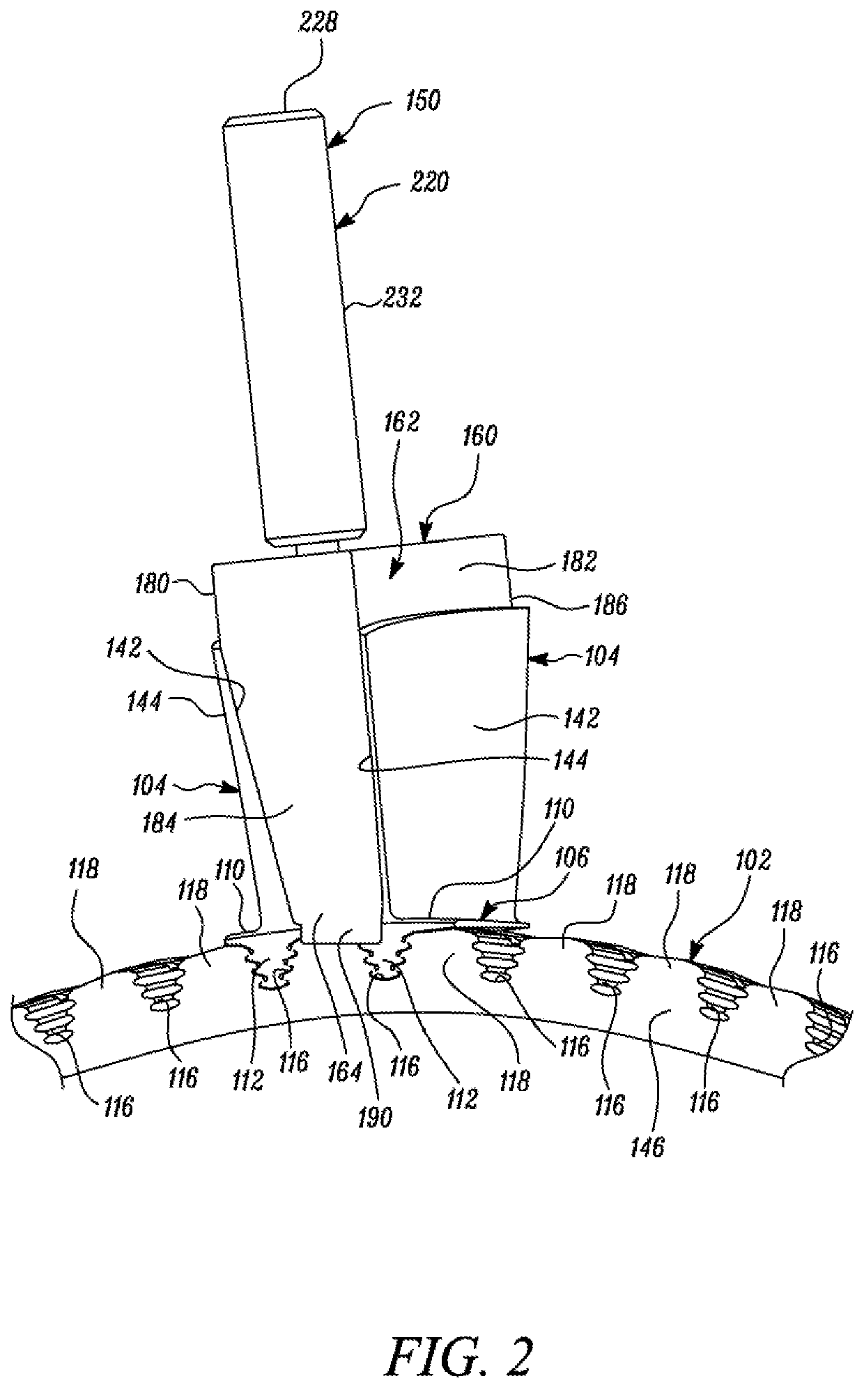
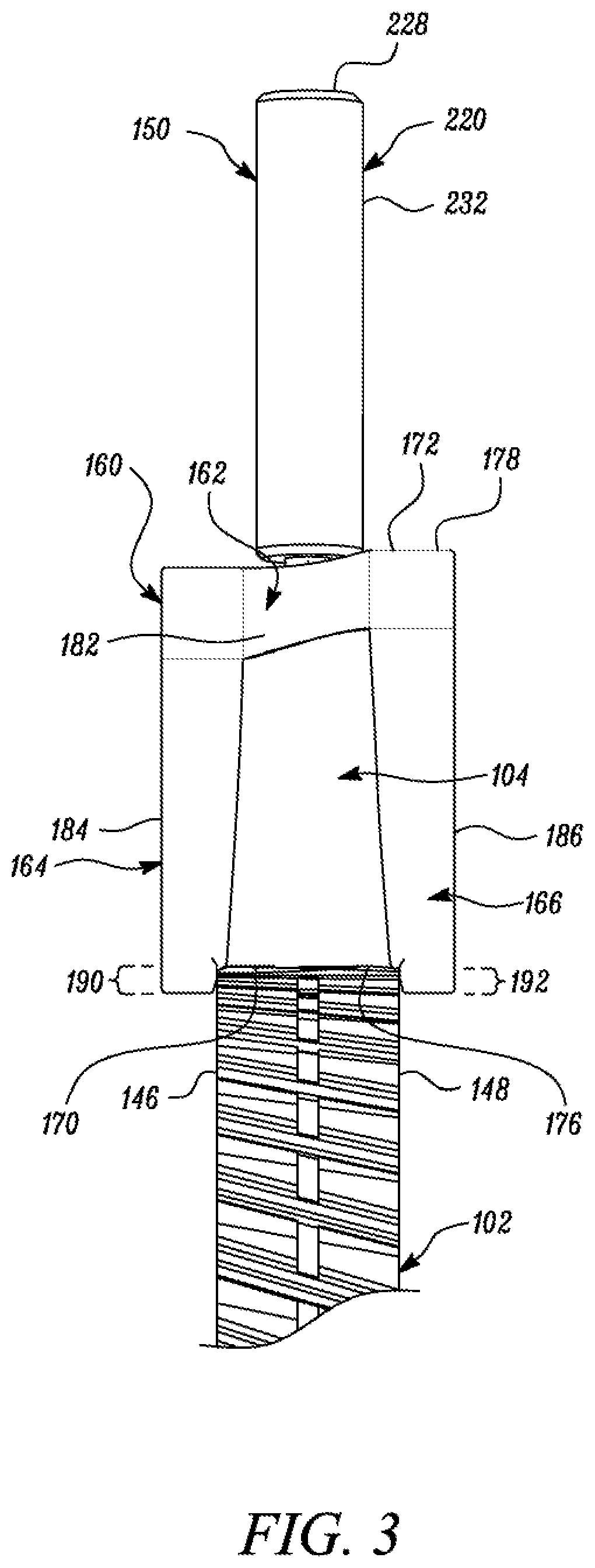
The present invention is a tool assembly for stacing a pin that connects a turbine blade to a turbine disk. The assembly includes a guide block that is positioned between the spaces between turbine blades. The guide block has a bottom surface that abuts the blade root of the turbine blade and a groove that runs through the guide block. This groove is designed to hold a portion of the pin that extends out from the blade root, making it easier to stake the pin. The technical effect of this invention is to make the staking process easier and more efficient in the production of turbine blades.

Problems solved by technology

Turbine blades and other components of GTEs are subject to high temperatures and high local stresses during operation.
However, as the punch is held in position manually, the punch may move away from the pin during staking and may hit and damage the turbine blade, which is undesirable.

Method used


Image

  • Staking tool assembly
  • Staking tool assembly
  • Staking tool assembly

Examples


Embodiment Construction

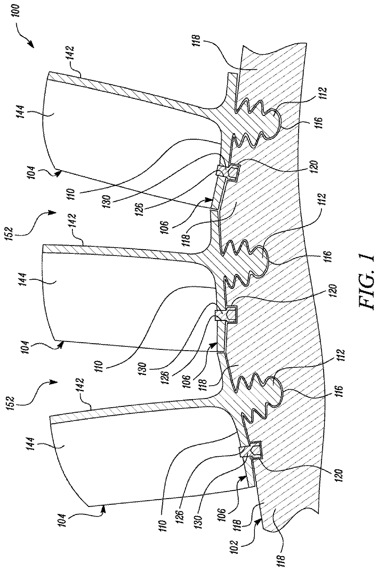
[0021]FIG. 1 is a cross-sectional view of a portion of a turbine 100 for example a gas turbine. The turbine 100 includes a turbine disk 102, and a plurality of turbine blades 104 mounted on the turbine disk 102. Each turbine blade 104 includes a blade root 106 having a platform 110 and a root structure 112 to be received in a correspondingly shaped cutout 116 in the turbine disk 102. As shown in FIG. 1, the root structure 112 may be configured as a dovetail. Although, the root structure 112 may be contemplated as the dovetail, other shapes of the root structure 112 and corresponding cutout 116 can be provided for each turbine blade 104 and the turbine disk 102, respectively. Each root structure 112 is received and supported between turbine disk posts 118 of the turbine disk 102. It should be noted that FIG. 1 shows clearances between the turbine disk 102 and the root structures 112 and platforms 110 for illustration purposes only. While these clearances may exist in the turbine 100,...


PUM


Abstract

A staking tool assembly for staking a pin coupling a turbine blade with a turbine disk is disclosed. The staking tool assembly includes a guide block configured to be positioned between a space defined between two consecutive turbine blades mounted on the turbine disk. The guide block includes a bottom surface configured to abut a blade root of the turbine blade. The guide block further includes a groove extending from the bottom surface through the guide block. The groove is configured to receive a portion of the pin extending outwardly from the blade root to facilitate a staking of the pin.

Description

TECHNICAL FIELD[0001]The present disclosure relates generally to a staking tool assembly and, more particularly, to a staking tool assembly for staking a pin coupling a turbine blade with a turbine disk.BACKGROUND[0002]Gas turbine engines (GTEs) produce power by extracting energy from a flow of hot gas produced by combustion of fuel in a stream of compressed air. In general, turbine engines have an upstream air compressor coupled to a downstream turbine with a combustion chamber (“combustor”) in between. Energy is released when a mixture of compressed air and fuel is burned in the combustor. The resulting hot gases are directed over blades of the turbine to spin the turbine and produce mechanical power.[0003]Turbine blades and other components of GTEs are subject to high temperatures and high local stresses during operation. Due to rotation of a turbine rotor disk supporting the turbine blades, the turbine blades experience a centrifugal force, and therefore must be retained within ...

Claims


Application Information

Patent Timeline
Patent Type & Authority Patents(United States)
IPC IPC(8): F01D5/32F01D5/02F01D5/12B25B27/02B25B31/00
CPCB25B27/02F01D5/326F01D5/02F05D2230/64F01D5/12B25B31/00B25B27/04
Inventor HOUCK, JAMES NEALWILLMON, JEWELL WINIFRED
Owner SOLAR TURBINES
Learn More