
Method for forming a hose comprising a flat web material as well as a hose formation device and a system for producing bags

a technology of forming device and hose, which is applied in the direction of paper/cardboard containers, box making operations, transportation and packaging, etc., can solve the problems of ugly web material, insufficient homogeneity of flat web material over its entire width and/or length, and the possibility of flawed later sacks or bags

Active Publication Date: 2020-01-07
WINDMOELLER & HOELSCHER GMBH
View PDF18 Cites 0 Cited by
  • Summary
  • Abstract
  • Description
  • Claims
  • Application Information

AI Technical Summary

Benefits of technology

The patent is about coating a flat web material with a high-quality coating that can be easily printed and acts as a moisture barrier. The material is then cut into small pieces to form a hose. The cuts are arranged in a staggered pattern to create tight bottoms for sacks or bags. The invention also addresses the issue of deviation during the hose formation process and provides a solution to ensure proper sealing of the bags or sacks. The technical effects of the invention include improved printing quality, moisture protection, and proper bag or sack formation.

Problems solved by technology

All of these tools are generally arranged fixed, however they may be displaced for adjusting the hose production.
However, it may also occur that the flat web material used is not sufficiently homogenous over its entire width and / or its entire length.
Due to the fact that in the hose formation device rather strong lateral forces may act upon the flat web material, here uncontrolled and thus undesired shifting of the material can occur perpendicular in reference to its direction of transportation, which leads to differently wide folds.
This is not only ugly when it is important for the prints to be correctly positioned with regards to the hose edges.
It is particularly problematic if prior to the hose formation the flat web material was processed for a later production of bags or sacks, however these processing positions were incorrectly arranged with regards to their location in reference to the edges of the hose.
The later sacks or bags may then be flawed.

Method used


Image

  • Method for forming a hose comprising a flat web material as well as a hose formation device and a system for producing bags
  • Method for forming a hose comprising a flat web material as well as a hose formation device and a system for producing bags

Examples


Embodiment Construction

[0031]Further scope of applicability of the present invention will become apparent from the detailed description given hereinafter. However, it should be understood that the detailed description and specific examples, while indicating preferred embodiments of the invention, are given by way of illustration only, since various changes and modifications within the spirit and scope of the invention will become apparent to those skilled in the art from this detailed description.

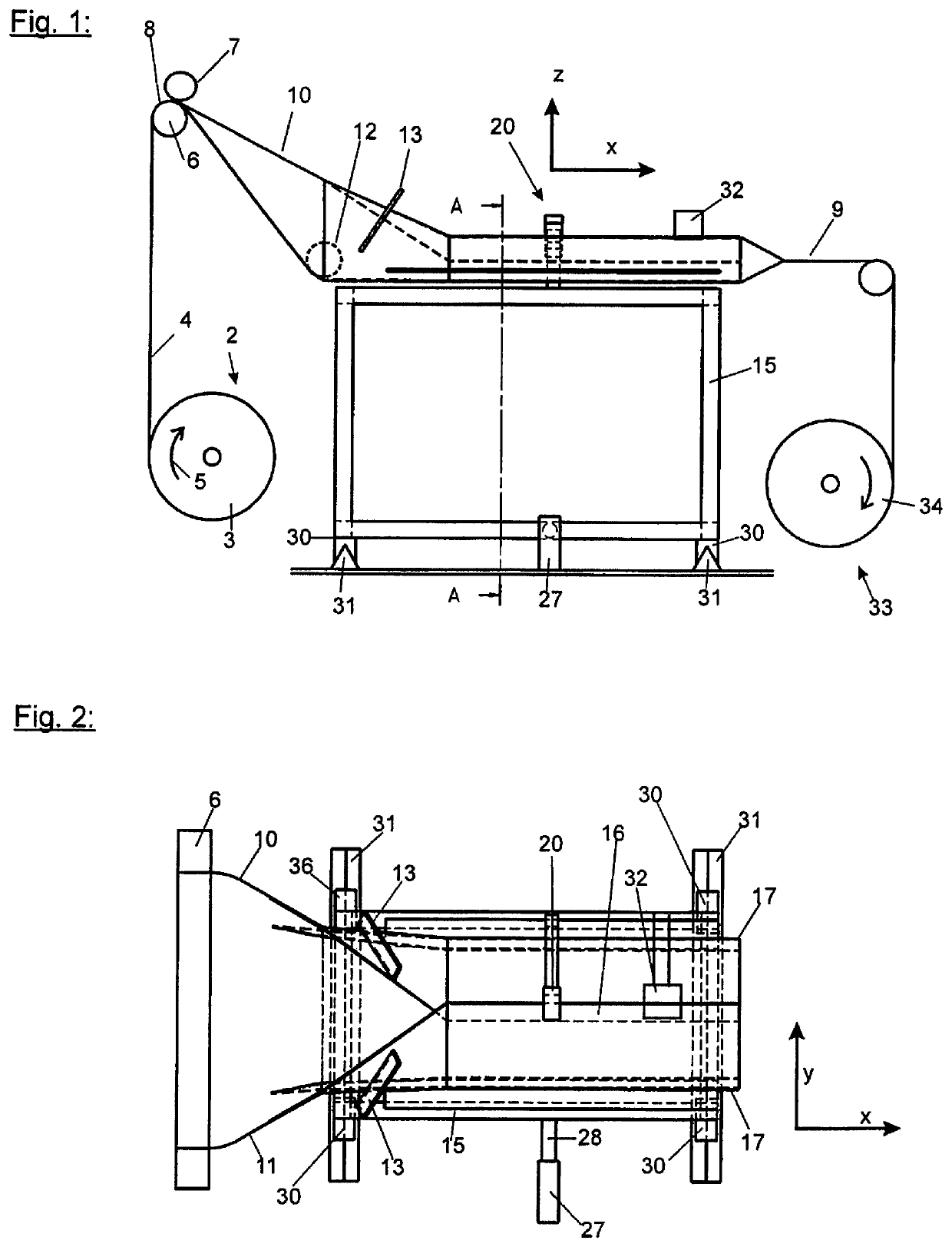
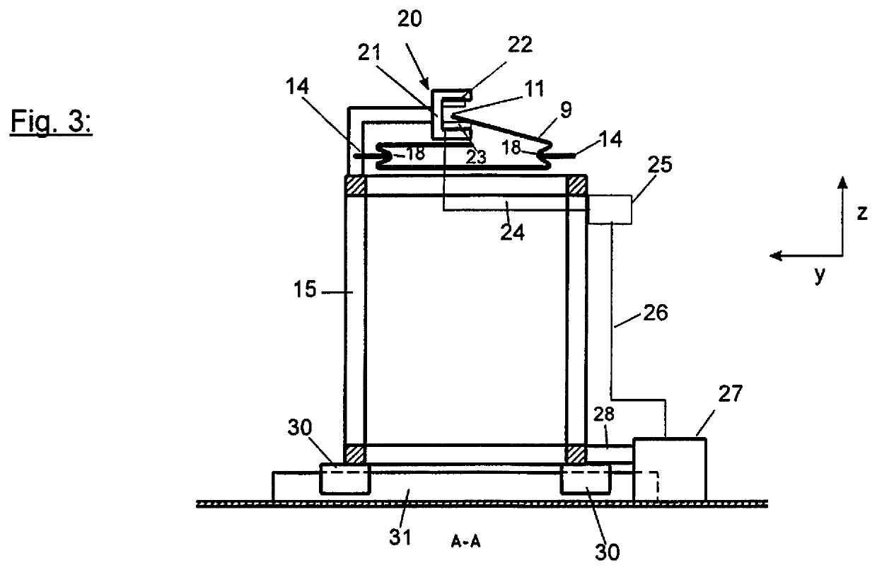
[0032]FIG. 1 shows a side view of a hose formation device 1 according to the invention. The hose machine comprising the hose formation device first comprises an unwinding device 2, in which a coil 3 of a flat web material 4 rotates in the direction of the arrow 5. The flat web material 4 is guided via a deflection roll 6, which represents a simple example of a feeding device of the flat web material 4 to the hose formation device 1.

[0033]The deflection roll 6 is shown in this exemplary embodiment as a counter rol...


PUM

PropertyMeasurementUnit
widthaaaaaaaaaa
plastic webaaaaaaaaaa
areaaaaaaaaaaa

Abstract

A method of forming a hose from a flat web material includes supplying the flat web material via a feeding device, folding the edges of the flat web material with at least one hose formation tool, with the edge sections subsequently overlapping, and connecting to each other parts of the overlapping edge sections, A target position of at least one edge is determined after the edges have been folded over, with the actual position of at least one edge being determined by a measuring device. In the event of a deviation of the actual position from the target position, the hose formation tool is moved, via an actuator, at least perpendicular relative to the direction of transportation of the flat web material.

Description

BACKGROUND OF THE INVENTION1. Field of the Invention[0001]The invention relates to a method for forming a hose made from a flat web material according to the preamble of claim 1 as well as a hose formation device according to the preamble of claim 9, Furthermore, the invention relates to a system for producing bags according to the preamble of claim 17.2. Description of Related Art[0002]Those sections are a semi-finished product during the production of bags and sacks, which frequently are separated from a hose, thus for example cut off or torn off. Such hoses are produced in a method and a device for producing a hose from a flat web material by this flat web being supplied via feeding devices, such as deflection rolls. The flat web material comprises here an area, which is limited by the lateral edges and / or borders. Then the borders, which are also called lateral edges, are folded inwardly by hose forming tools, namely such that the edge sections overlap each other. Parts of the o...

Claims


Application Information

Patent Timeline
Patent Type & Authority Patents(United States)
IPC IPC(8): B65H35/04B31B70/00B65H23/02B31B70/64B31B70/36B31B70/26B31B50/36B31B155/00B31B160/20
CPCB31B70/00B65H35/04B65H23/02B31B70/266B31B70/36B31B70/64B31B2160/20B31B2155/0012B65H2701/191B65H2301/41487B31B2155/00
Inventor WOLFRAM, UWE
Owner WINDMOELLER & HOELSCHER GMBH
Learn More