Picture hanging device
- Summary
- Abstract
- Description
- Claims
- Application Information
AI Technical Summary
Benefits of technology
Problems solved by technology
Method used
Image
Examples
example 1
[0242]In an embodiment, the stud finder can have a Beginning Operation method having the steps below.
[0243]Step 1: Place the stud finder on the wall 3500 and turn it on.
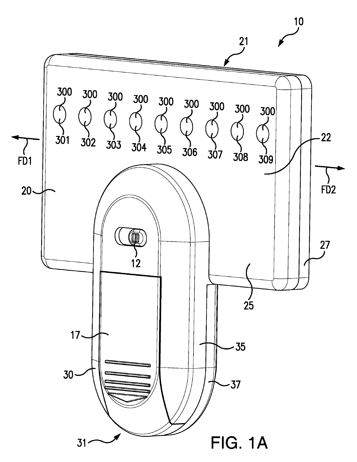
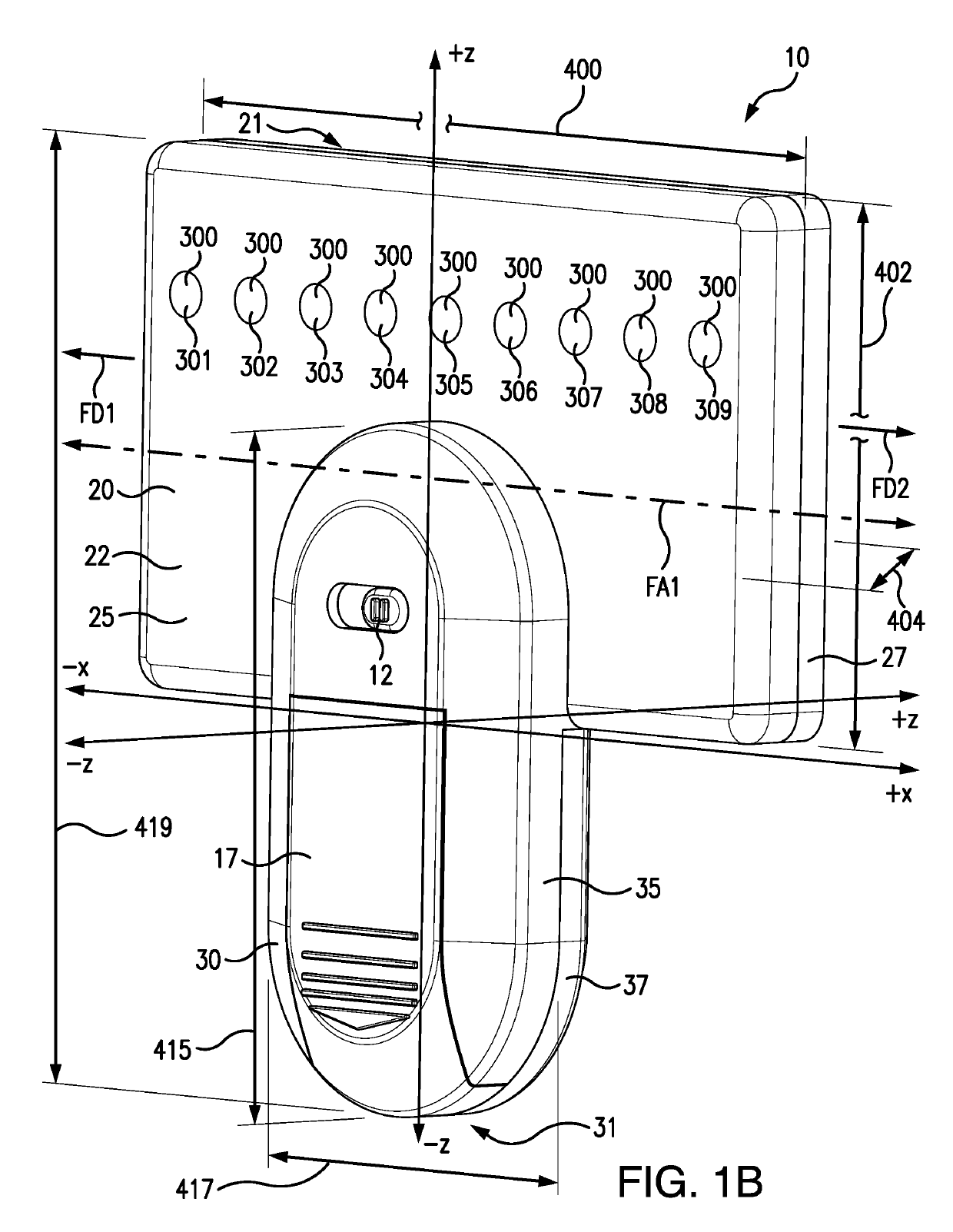
[0244]Step 2: Once the unit is on, the capacitive plates will send readings to the microprocessor. The microprocessor will compare the capacitive values and the plates with a higher value will indicate a stud. In this example, capacitive plates 2, 3, and 4 in FIG. 16 are over a stud so they will read a high capacitive value. Capacitive plates 1, 5, 6, 7, 8, and 9 are not over a stud so they will read low capacitive values in comparison to the values of capacitive plates 2, 3, and 4. The unit will not turn on any LEDs though aside from the power light indicator.
[0245]Step 3: The unit will only turn on LEDs when a capacitive value changes from low to high.
[0246]Step 4: As the stud finder is moved to the left, as shown in FIG. 16, sensor plates 3 and 4 remain high capacitive values and 1, 6-9 remain low capacitive value...
example 2
[0265]In an embodiment, the stud finder can have an Edge of Stud Finder Operation method having the steps below.
[0266]Step 1: When the sensor plates do not indicate any plates with high capacitance, the unit will not display any LEDs
[0267]Step 2: As the unit approaches the edge of a stud, the outside edge sensor plate (sensor plate 1) will change from low to high capacitance and the corresponding LED will turn on
[0268]Step 3: As the unit moves further across the stud, the second sensor plate will also change from low to high capacitance and the corresponding LED will also turn on
[0269]Step 4: Only the 2 sensor plates on each end can display their LEDs without being a complete set of three. If only one or two central sensor plates indicate high capacitance but the other adjacent sensors indicate low capacitance, than the three closest LEDs to the central highest capacitance value will turn on.
[0270]FIG. 19 is a schematic showing the stud finder moving toward a stud.
[0271]FIG. 20 is a...
example 3
[0277]In an embodiment, the stud finder can have a Two Separate Stud Operation method having the steps below.
[0278]Step 1: When two separate groups of sensor plates indicate high capacitance, the unit will display the left group of three LEDs for 0.2 seconds.
[0279]Step 2: The unit will have a 0.05 second delay, displaying no studs.
[0280]Step 3: The unit will then display the right group of three LEDs corresponding with the right group of sensor plates indicating high capacitance for 0.2 seconds, and then have another 0.05 second delay displaying no studs before repeating.
[0281]In another example, when multiple studs are sensed, the stud finder can communicate the following display of LEDs:
[0282]Step 1: Turn the 3 LEDs associated with the left stud on for 0.2 seconds;
[0283]Step 2: Turn off all LEDs for 0.05 seconds;
[0284]Step 3: Turn the 3 LEDs associated with the right stud on for 0.2 seconds;
[0285]Step 4: Turn off all LEDs for 0.05 seconds; and
[0286]Step 5: Repeat, on optional numb...
PUM
 Abstract
Description
Claims
Application Information
 - R&D
- Intellectual Property
- Life Sciences
- Materials
- Tech Scout
- Unparalleled Data Quality
- Higher Quality Content
- 60% Fewer Hallucinations
Browse by: Latest US Patents, China's latest patents, Technical Efficacy Thesaurus, Application Domain, Technology Topic, Popular Technical Reports.
© 2025 PatSnap. All rights reserved.Legal|Privacy policy|Modern Slavery Act Transparency Statement|Sitemap|About US| Contact US: help@patsnap.com


