
Laser-powered ice-penetrating communications delivery vehicle for sub-ice submarine missions

a communication delivery vehicle and submarine technology, applied in the field of communication devices, to achieve the effect of reducing the time to field this system, rapid deployment, and advance in tactical capability

Active Publication Date: 2019-12-31
STONE AEROSPACE INC
View PDF3 Cites 4 Cited by
  • Summary
  • Abstract
  • Description
  • Claims
  • Application Information

AI Technical Summary

Benefits of technology

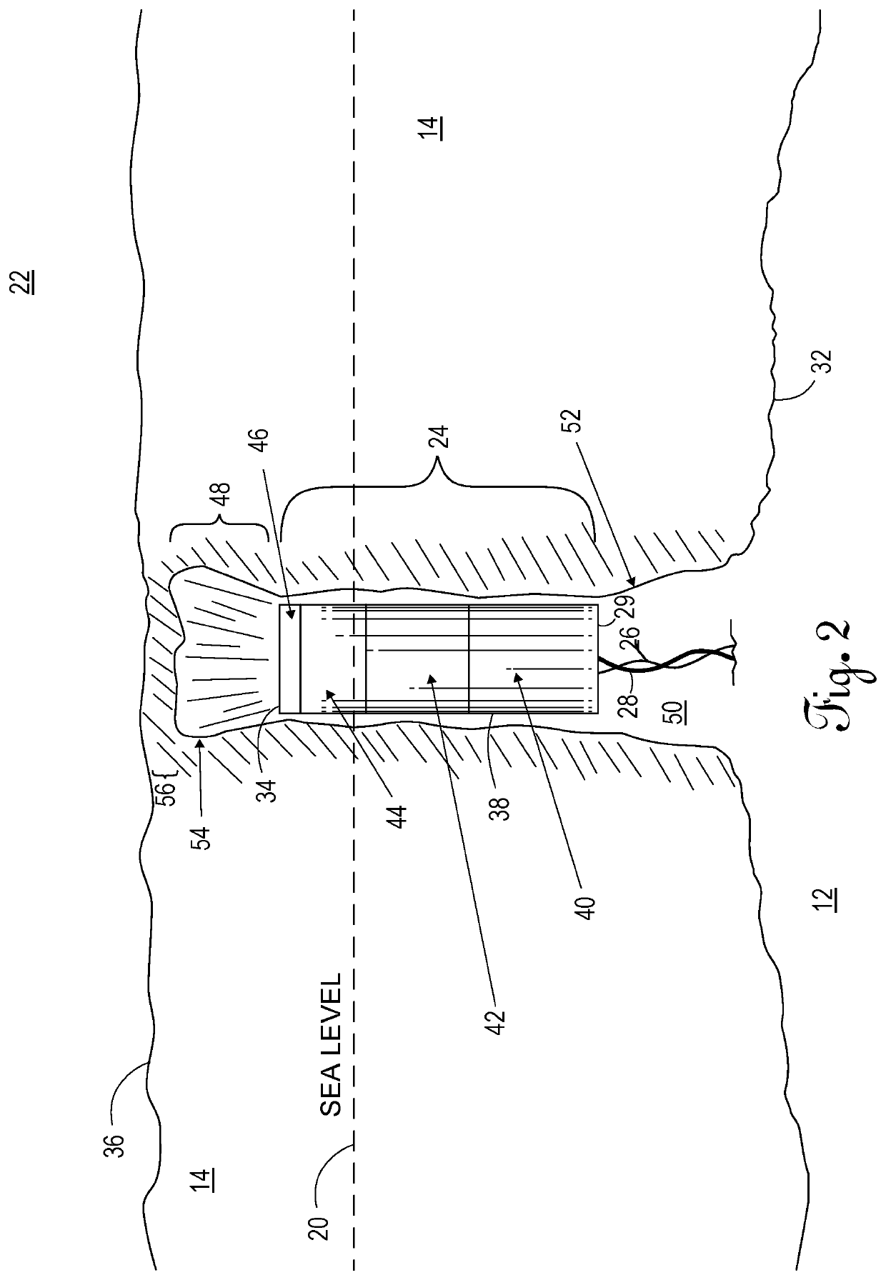
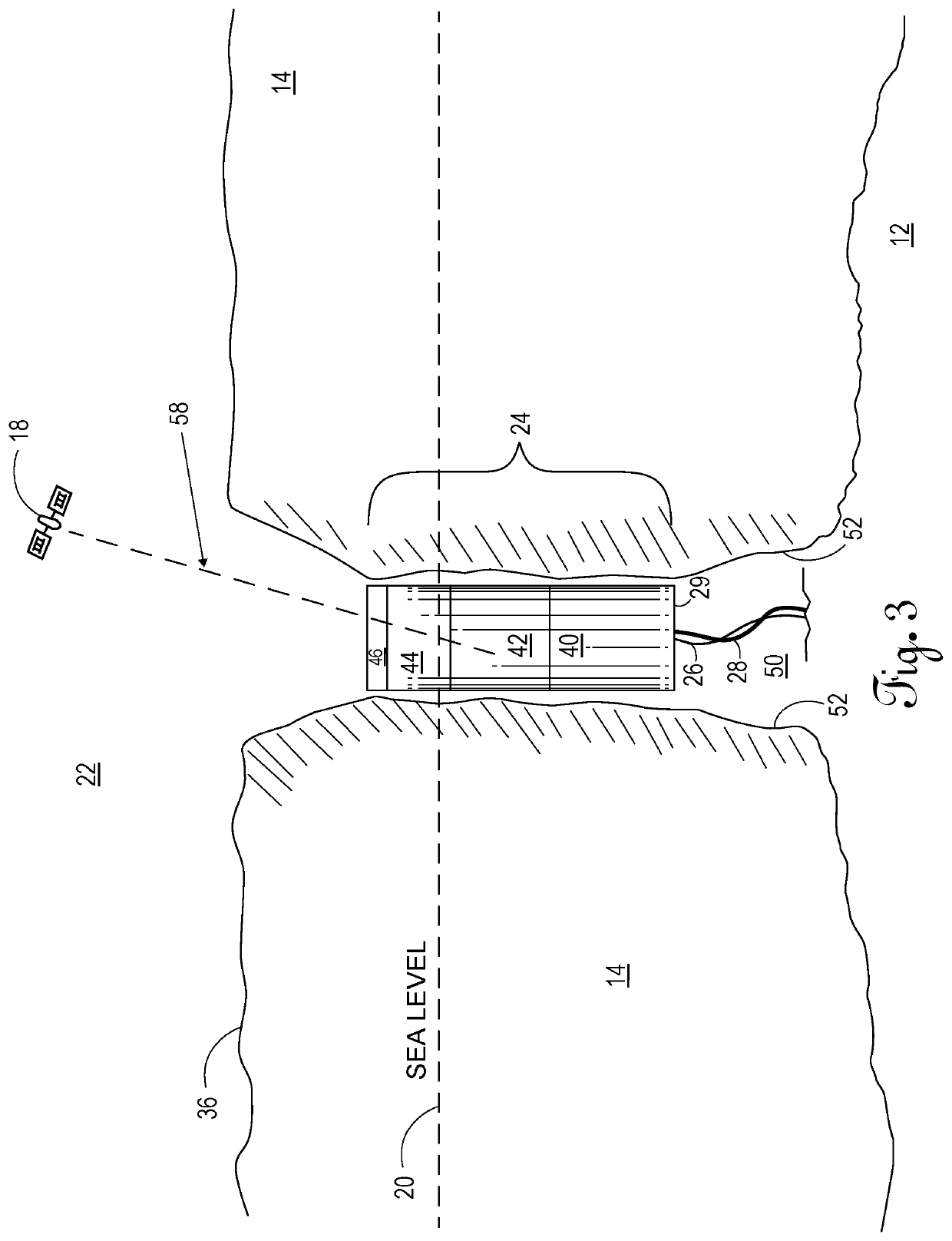
[0007]The present invention is a laser powered, ice penetrating system with a vehicle that can deliver a communication payload (or other payload) through a thick ice sheet, through an overlying firn layer (snow left over from prior seasons and recrystallized into a substance denser than névé, which is partially melted, refrozen and compacted snow preceding ice formation), and to the clear surface exposed to atmosphere, thus allowing high bandwidth, bi-directional communication between satellite networks, ground level communication systems, and large under-ice vehicles.
[0028]The communications payload delivery system of the present invention is compact and deploys rapidly. The present invention represents a significant advance in tactical capability and fills a large operational void that has existed since submarines have been conducting under ice operations. Additionally, the ice melting system of the present invention is relatively silent and does not utilize any energetic or pyrotechnic materials that would be hazardous to store or handle on a sub-ice vessel, i.e., the submarine, thus reducing the time to field this system. The present invention advantageously does not utilize chemical heating (e.g., thermite or sodium or the like) resulting in safe handling and operations.

Problems solved by technology

Yet, even at this high level of power, the laser unit is compact enough to be installed practically aboard submarines with constrained hatch sizes and limited onboard space.

Method used


Image

  • Laser-powered ice-penetrating communications delivery vehicle for sub-ice submarine missions
  • Laser-powered ice-penetrating communications delivery vehicle for sub-ice submarine missions
  • Laser-powered ice-penetrating communications delivery vehicle for sub-ice submarine missions

Examples


Embodiment Construction

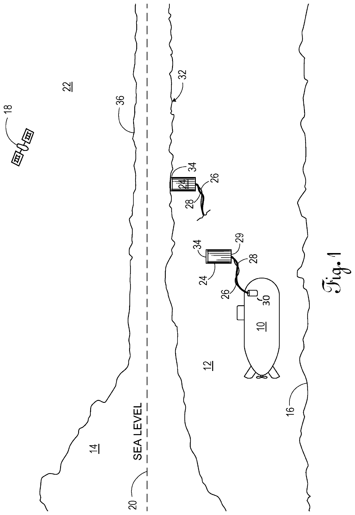
[0037]Referring to FIG. 1, sub-ice vessel 10 traverses ocean water 12 under ice shelf 14 (or ice mass 14, or ice sheet 14) and above ocean floor 16 in sub-freezing waters. Satellite 18 orbits above the earth in open atmosphere 22. Ice shelf 14 may extend several meters (e.g., 100 meters up to 1000 meters) above sea level 20, having substantial ice mass thickness between bottom surface 32 and ice surface 36 of ice shelf 14. Consequently, communication between sub-ice vessel 10 and satellite 18 is little to none, as it is difficult to transmit or receive a signal through ice shelf 14 in this harsh environment.

[0038]Communication delivery vehicle 24 is releasably engaged to sub-ice vessel 10. More particularly, communication delivery vehicle 24 is stored within launch tube 30 externally attached to sub-ice vessel 10. Communication delivery vehicle 24 is tethered to sub-ice vessel 10 via process fiber 28 (power fiber) and communication optic line 26. Desirous of establishing communicati...


PUM


Abstract

A laser-powered ice-penetrating communications payload delivery vehicle for sub-ice submarine missions enables under-ice operations to exchange information with terrestrial facilities or satellite networks with communications methods otherwise blocked by an ice cap. The vehicle comprises an electronics bay, a payload bay, optics bay, and a melt optic with laser. The system and method of establishing communication where the vehicle, tethered to a sub-ice vessel, is released. The vehicle ascends to the bottom of an ice sheet and uses a laser to melt the ice, forming a borehole through which the vehicle continues to ascend. When buoyancy no longer advances the vehicle beyond sea level, the vehicle continues to melt a conical opening through the ice until unobstructed atmosphere is reached and bi-directional communication is established. Where the melting capacity cannot reach ice to continue melting, the vehicle mechanically advances itself toward the surface to establish high bandwidth, bi-directional communication.

Description

CROSS REFERENCE TO RELATED APPLICATIONS[0001]This original non-provisional application claims priority to and the benefit of U.S. provisional application Ser. No. 62 / 625,159, filed Feb. 1, 2018, and entitled “Laser-Powered Ice-Penetrating Communications Antenna for Sub-Ice Submarine Missions,” which is incorporated by reference herein.STATEMENT REGARDING FEDERALLY SPONSORED RESEARCH OR DEVELOPMENT[0002]None.BACKGROUND OF THE INVENTION1. Field of the Invention[0003]The present invention relates to communication devices, and more specifically to laser-powered ice-penetrating communications delivery vehicles for sub-ice submarine missions.2. Description of the Related Art[0004]Currently, submarines deploy tethered buoyant communications antennas, which come to rest on the underside of the ice shelf. These antennas can receive radio communications from above the ice at very low bandwidth, but have no transmitting capability. The lack of transmitting capabilities is due to poor radio fre...

Claims


Application Information

Patent Timeline
Patent Type & Authority Patents(United States)
IPC IPC(8): B63C11/52B63G8/38
CPCB63G8/38B63C11/52B63B2203/00B63B2211/06
Inventor HARMAN, JOHNSTONE, WILLIAM C.
Owner STONE AEROSPACE INC
Learn More