Rotary jet, power generation systems and motors including the same, and methods of making and using the same

a technology of rotary jets and motors, applied in the direction of renewable energy generation, vessel construction, greenhouse gas reduction, etc., can solve the problems of high purchase price and maintenance costs, large space occupation of materials and equipment, and excessive design changes or excessive costs, and achieves easy maintenance and maintenance. , the effect of avoiding significant pollution or environmental impa

Active Publication Date: 2019-12-17
LEE BRENT WEI TEH
View PDF28 Cites 1 Cited by
  • Summary
  • Abstract
  • Description
  • Claims
  • Application Information

AI Technical Summary

Benefits of technology

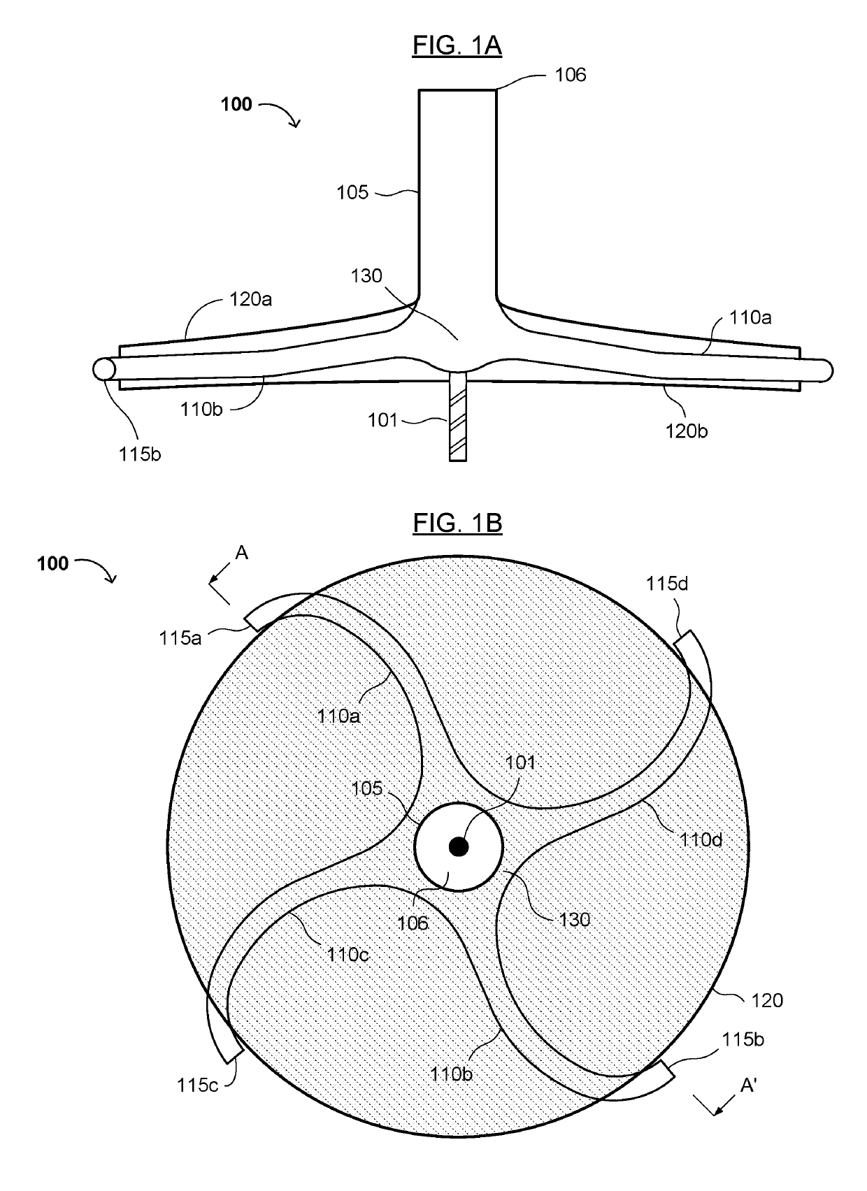
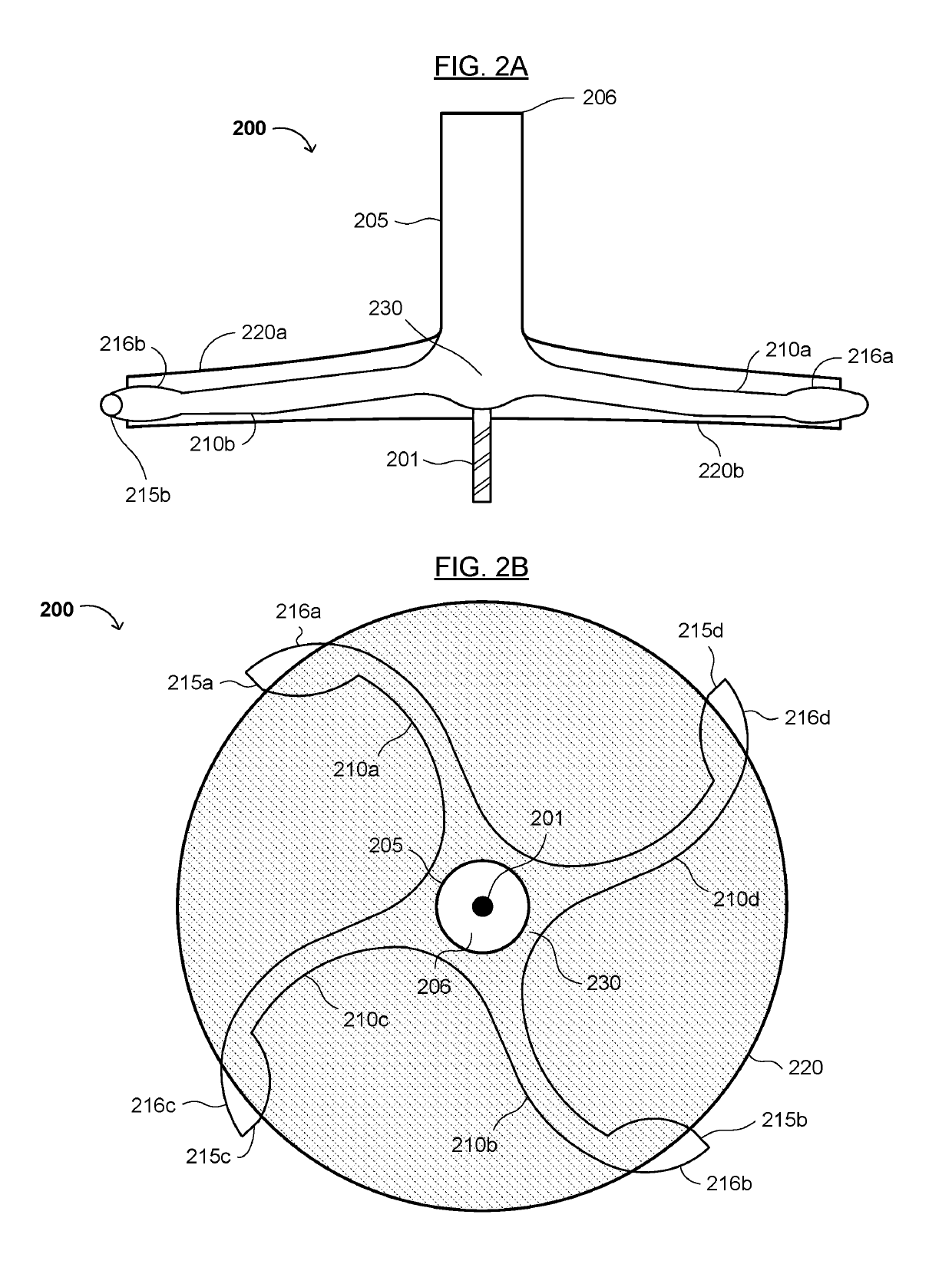
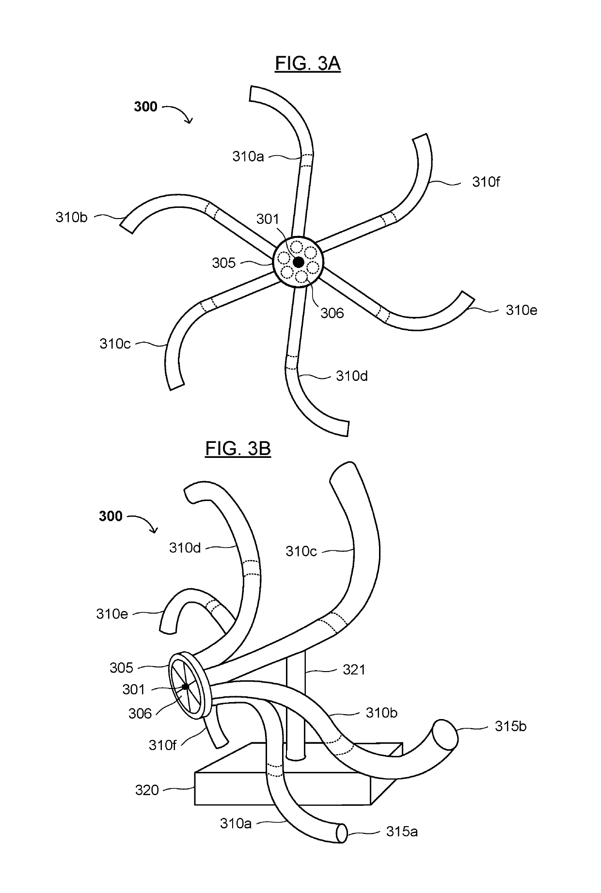
[0005]The present invention relates to a novel rotary device (e.g., a rotary jet), power generation systems and motors including the same, and methods of manufacturing and using the same. The present rotary jet advantageously generates or uses a rotational driving force to make electricity (in some cases, without combustible materials) and to transport or move fluids such as air or water efficiently. The present rotary jet also advantageously utilizes a self-amplifying rotary motion or movement that may increase the net thrust of the device. As a result, the present rotary jet may be more efficient and may have less wear and tear than conventional power generating devices such as engines, and may have fewer and less expensive parts subject to such wear and tear.
[0015]The present rotary jet may be adapted for power generation (e.g., hydraulic power, gas [combustion] power, or wind power), fluid transportation devices (e.g., a vacuum pump, vacuum cleaner, water pump, air compressor or water jet) or other mechanical drive applications (e.g., milling or in various types of vehicles such as automobiles, boats, ships, planes, drones, etc., using air or water jet propulsion). Thus, the novel rotary jet can be integrated into conventional power generation systems, fluid transportation devices, and mechanical drive applications without extensive design changes or excessive cost. Also, the present invention may provide a continuous energy supply without significant pollution or environmental impact.
[0016]The present rotary jet advantageously is relatively simple in comparison to conventional fluid transporters and energy converters. Having as few as one moving part allows the present invention to be relatively easy to maintain and simple to construct. The present rotary jet has an excellent balance of cost and function, and is based on a relatively simple design that performs relatively well and at a relatively low or minimal cost. The present rotary jet may be operated using a variety of widely and / or naturally available fluids (e.g., air, steam, water, and other gases and liquids). These and other advantages of the present invention will become readily apparent from the detailed description of various embodiments below.

Problems solved by technology

However, these technologies generally require combustible material (e.g., fuel, oil and / or coal) and expensive equipment (e.g., in terms of purchase price and maintenance costs).
In addition, such material and equipment may consume a lot of space, requiring use of a large amount of ground are or real estate and driving up costs.
Furthermore, these technologies may cause air and noise pollution and global warming.

Method used


Image

  • Rotary jet, power generation systems and motors including the same, and methods of making and using the same
  • Rotary jet, power generation systems and motors including the same, and methods of making and using the same
  • Rotary jet, power generation systems and motors including the same, and methods of making and using the same

Examples


Embodiment Construction

[0040]Reference will now be made in detail to various embodiments of the invention, examples of which are illustrated in the accompanying drawings. While the invention will be described in conjunction with the following embodiments, it will be understood that the descriptions are not intended to limit the invention to these embodiments. On the contrary, the invention is intended to cover alternatives, modifications and equivalents that may be included within the spirit and scope of the invention. Furthermore, in the following detailed description, numerous specific details are set forth in order to provide a thorough understanding of the present invention. However, it will be readily apparent to one skilled in the art that the present invention may be practiced without these specific details. In other instances, well-known methods, procedures, components and materials have not been described in detail so as not to unnecessarily obscure aspects of the present invention.

[0041]Thus, th...


PUM


Abstract

A rotary device (e.g., a rotary jet), power generation system, and methods of manufacturing and using the same are disclosed. The rotary jet includes a central axle or shaft, an inlet configured to receive at least one fluid, and a plurality of radial arms in fluid communication with the inlet, configured to rotate around the central axle or shaft. Each radial arm has a nozzle at a distal end thereof and an arc between the inlet and the nozzle. The radial arms extend radially from the central axle or shaft at least in part, and are configured to rotate when the fluid enters the inlet and passes through the radial arms, or when a rotational force is applied to the central axle or shaft. Each nozzle may have an opening facing away from a direction of rotation of the radial arms or facing in a direction parallel with the central axle or shaft.

Description

CROSS REFERENCE TO RELATED APPLICATION[0001]This application claims the benefit of U.S. Provisional Patent Application Nos. 62 / 389,963, 62 / 390,756, and 62 / 391,840 filed on Mar. 14, 2016, Apr. 8, 2016, and May 12, 2016, respectively, which are incorporated herein by reference as if fully set forth herein.FIELD OF THE INVENTION[0002]The present invention generally relates to the field of rotary devices, power generation and power-driven devices (e.g., motors). More specifically, embodiments of the present invention pertain to a novel rotary fluid transporter (e.g., a “rotary jet”), power generation systems and motors including the same, and methods of manufacturing and using the same.DISCUSSION OF THE BACKGROUND[0003]Most conventional power generation involves engines and motors. However, these technologies generally require combustible material (e.g., fuel, oil and / or coal) and expensive equipment (e.g., in terms of purchase price and maintenance costs). In addition, such material an...

Claims


Application Information

Patent Timeline
Patent Type & Authority Patents(United States)
IPC IPC(8): F01D1/32F02K7/00F03B3/08B63H11/04F02C3/16F03D15/00F03D1/06B63H11/12B63H11/08
CPCF02K7/005F03D15/05B63H11/08F03D1/0625F02C3/165F01D1/32F03B3/08B63H11/12Y02P70/525Y02T50/671Y02E10/223Y02P70/523Y02E10/721B63H2011/082Y02E10/20Y02E10/72Y02P70/50Y02T50/60
Inventor LEE, BRENT WEI-TEH
Owner LEE BRENT WEI TEH
Why Eureka
Try Eureka