
Kneader and manufacturing method of electrode body including electrode active material using the same

a manufacturing method and active material technology, applied in the field of knives, can solve the problems of poor application, affecting the manufacture of the electrode body, and the viscosity of the active material paste to be obtained is not necessarily uniform, and achieves the effects of stable viscosity and the like of the active material paste to be obtained, high solid content ratio, and easy unevenness in viscosity and the lik

Active Publication Date: 2019-12-03
TOYOTA JIDOSHA KK
View PDF24 Cites 0 Cited by
  • Summary
  • Abstract
  • Description
  • Claims
  • Application Information

AI Technical Summary

Benefits of technology

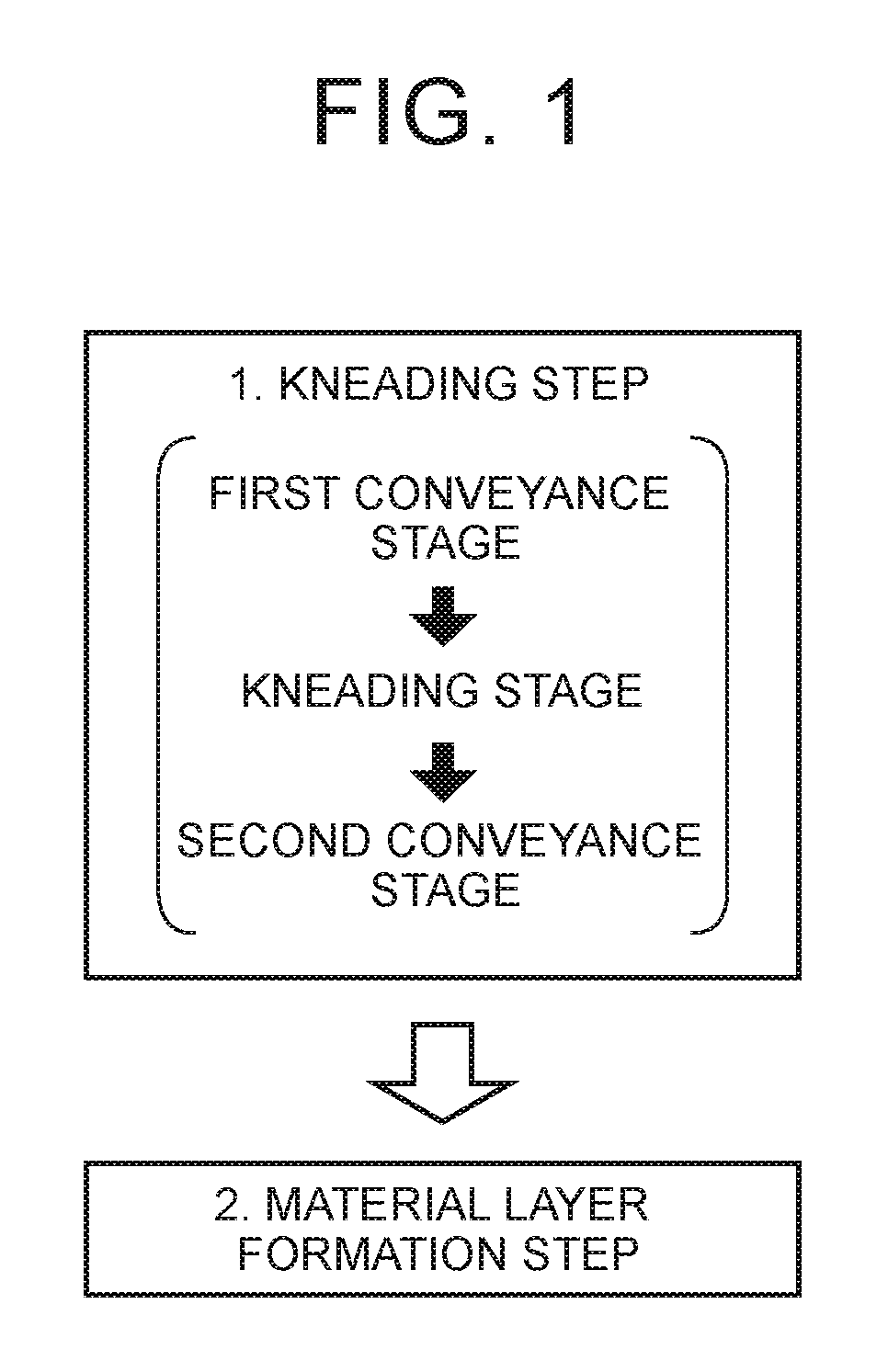
This patent is about a kneader that makes a more even mixture of materials, and a method for making a stable electrode body using a smooth electrode active material paste. The kneader has two screw blades with different outside diameters, which creates a stronger conveyance force in the second conveyance zone. This ensures that the kneaded mixture has less unevenness in viscosity. By using this kneader, the electrode body can be made with high quality and stability. The solid content ratio of the material to be combined should be 60% or higher to ensure a stable electrode active material paste. Overall, this patent provides a solution for manufacturing high-quality electrode bodies with consistent viscosity.

Problems solved by technology

However, the above technique described above has the following problem.
A viscosity of the electrode active material paste to be obtained is not necessarily uniform.
Because of this, in a case where the electrode active material paste to be obtained is used for application as it is, poor application may be caused due to an unexpected abnormal viscosity.
This affects the manufacture of the electrode body.
Particularly, when a solid content ratio in a raw material for kneading to obtain an electrode active material paste is set rather high, such a problem tends to easily occur.
When the kneader is driven in a high-speed rotation state such as a double speed, a similar problem also tends to easily occur.

Method used


Image

  • Kneader and manufacturing method of electrode body including electrode active material using the same
  • Kneader and manufacturing method of electrode body including electrode active material using the same
  • Kneader and manufacturing method of electrode body including electrode active material using the same

Examples


examples

[0057]The following describes Examples. In Examples, in terms of a kneading material, the afore-mentioned material used to manufacture the negative-electrode active material paste was used, and a target viscosity of a negative-electrode active material paste to be obtained was set to 4000 mPa·s. Further, the following two process conditions were employed.[0058]Discharge flow rate: 0.7 L / m (axis rotation speed: 600 rpm)[0059]Discharge flow rate: 1.4 L / m (axis rotation speed: 1200 rpm)

[0060]Details of Comparative Examples 1 and 2 and Examples 1 to 4 are shown in Table 1. In Table 1, three items, i.e., “Solid Content”, “Discharge Flow Rate,” and “Screw Outside Diameter Ratio” are shown as manufacturing conditions for respective examples, and four items, i.e., “Paste Viscosity”, “Viscosity Variation,”“Residual Solid Content Variation,” and “Evaluation” are shown as results. First described are these items.

[0061]“Solid Content” indicates a weight ratio of a solid content in a kneading ma...


PUM

PropertyMeasurementUnit
viscosityaaaaaaaaaa
viscosityaaaaaaaaaa
viscosityaaaaaaaaaa

Abstract

A kneader has a rotational conveyance member configured to knead the kneading material and convey the kneading material from an inlet toward an outlet by a rotational motion around an axis. The rotational conveyance member has a kneading zone configured to knead the kneading material, a first conveyance zone placed on an upstream side relative to the kneading zone and configured to convey the kneading material, and a second conveyance zone placed on a downstream side relative to the kneading zone and configured to convey the kneading material, and a conveyance force of the second conveyance zone is smaller than a conveyance force of the first conveyance zone in a case where the same conveyance object is conveyed.

Description

INCORPORATION BY REFERENCE[0001]The disclosure of Japanese Patent Application No. 2015-168494 filed on Aug. 28, 2015 including the specification, drawings and abstract is incorporated herein by reference in its entirety.BACKGROUND OF THE INVENTION[0002]1. Field of the Invention[0003]The present invention relates to a kneader for kneading a kneading material so as to obtain a pasty kneaded mixture, and a manufacturing method for manufacturing an electrode body including an electrode active material by manufacturing an electrode active material paste by use of the kneader. More specifically, the present invention relates to a kneader that reduces unevenness in viscosity of an obtained kneaded mixture, and a manufacturing method for manufacturing an electrode body including an electrode active material by using an electrode active material paste obtained by use of the kneader and having less unevenness in viscosity.[0004]2. Description of Related Art[0005]Conventionally, an electrode a...

Claims


Application Information

Patent Timeline
Patent Type & Authority Patents(United States)
IPC IPC(8): H01M4/04B01F7/04B01F7/08B29C48/57H01M4/1393H01M4/133H01M4/62H01M4/587H01M4/139
CPCB29C48/57H01M4/0404H01M4/0411H01M4/04H01M4/1393B01F7/04B01F7/08H01M4/587H01M4/622H01M4/133H01M4/139B01F27/72B01F35/71705B01F35/71H01M10/052B29B7/483B29B7/488B29B7/489Y02E60/10Y02P70/50B01F27/70B01F2101/59
Inventor SUGIHARA, ATSUSHI
Owner TOYOTA JIDOSHA KK
Learn More