Sheet accommodating device and image forming apparatus including the same
a technology of accommodating device and image forming apparatus, which is applied in the direction of electrographic process, instruments, transportation and packaging, etc., can solve the problems of deterioration in the pressure accuracy of the pressing force of sheets
- Summary
- Abstract
- Description
- Claims
- Application Information
AI Technical Summary
Benefits of technology
Problems solved by technology
Method used
Image
Examples
first embodiment
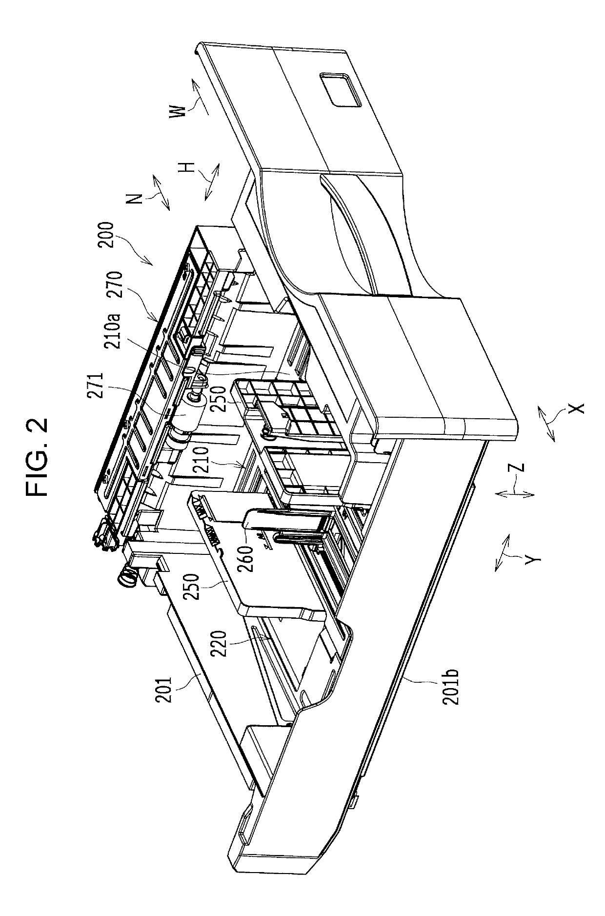
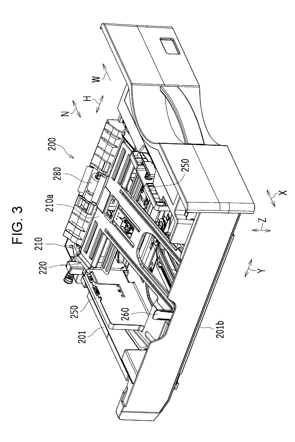
[0031]The sheet accommodating device 200 includes a first plate member 210 (see FIGS. 2 to 9 and 11), a first biasing member 230 (see FIGS. 5 to 7), a second plate member 220 (see FIGS. 2 to 8, 10, and 11), and a second biasing member 240 (see FIGS. 6 and 7). The first plate member 210 is a member on which sheets are mounted. The first biasing member 230 is provided between the first plate member 210 and a bottom member 201b (see FIGS. 2 and 3) of a housing 201 (see FIGS. 2 and 3) and presses up the first plate member 210. The second plate member 220 is disposed on a side of the first plate member 210 opposite to a side of the first plate member 210 on which the sheets are mounted. The second biasing member 240 is provided between the second plate member 220 and the bottom member 201b of the housing 201 and presses up the second plate member 220. This enables the second biasing member 240 to press up the first plate member 210, which has been pressed up by the first biasing member 2...
second embodiment
[0060]FIG. 12 is a schematic plan view showing other examples of the first and second plate members 210 and 220. FIG. 13 is a schematic plan view showing the first plate member 210 shown in FIG. 12. Further, FIG. 14 is a schematic plan view showing the second plate member 220 shown in FIG. 12.
[0061]The dimension L of the predetermined region of the front-end side of the first plate member 210 in the width direction H is not limited to the dimension of the first embodiment, but, as shown in FIG. 12, may be smaller than a dimension of a sheet of a maximum accommodatable size (in this example, A4 size or 8½ size) in the width direction H during the second upward pressing action. The predetermined region of the front-end side of the first plate member 210 is located in the center in the width direction H. For example, the dimension L may be such a dimension (e.g. a dimension of a B5-size sheet in the width direction H) that both end portions of a sheet of a maximum accommodatable size (...
third embodiment
[0062]Incidentally, if, in a case where the first fulcrum axis line α of the first plate member 210 is located in a lower position than the second fulcrum axis line β of the second plate member 220, the first fulcrum axis line α of the first plate member 210 is provided in a position further away from the front end of a sheet that is mounted on the first plate member 210 than the second fulcrum axis line β of the second plate member 220 in a state where both the first and second plate members 210 and 220 are located in the lowest position, it is necessary to lower the bottom member 201b of the housing 201 in order to prevent a portion of the first fulcrum axis line α of the first plate member 210 from coming into contact with the bottom member 201b of the housing 201 when the second plate member 220 turns upward, and to that extent, upsizing of the sheet accommodating device 200 is invited. Accordingly, it is desirable not to lower the bottom member 201b.
[0063]FIG. 15 is a schemati...
PUM
| Property | Measurement | Unit |
|---|---|---|
| size | aaaaa | aaaaa |
| area | aaaaa | aaaaa |
| width | aaaaa | aaaaa |
Abstract
Description
Claims
Application Information
 - R&D
- Intellectual Property
- Life Sciences
- Materials
- Tech Scout
- Unparalleled Data Quality
- Higher Quality Content
- 60% Fewer Hallucinations
Browse by: Latest US Patents, China's latest patents, Technical Efficacy Thesaurus, Application Domain, Technology Topic, Popular Technical Reports.
© 2025 PatSnap. All rights reserved.Legal|Privacy policy|Modern Slavery Act Transparency Statement|Sitemap|About US| Contact US: help@patsnap.com


