
Air pressure control device and adjustment valve

a control device and air pressure technology, applied in fluid pressure control, process and machine control, instruments, etc., can solve the problems of noisy exhaust sounds, unstable output pressure, and bringing about loss of energy, and achieve high reliability, small energy loss, and high accuracy

Active Publication Date: 2019-11-19
YAMATAKE HONEYWELL CO LTD
View PDF39 Cites 0 Cited by
  • Summary
  • Abstract
  • Description
  • Claims
  • Application Information

AI Technical Summary

Benefits of technology

[0022]With intent to solve the above-described problems, an object of the present disclosure is to provide an air pressure control device in which a valve seat supported by a diaphragm is displaced correctly without suffering from influences of behaviors of a compression coil spring when it is compressed or extended, and in which an exhaust leak and a failure of pressure adjustment do not occur, and is to provide an adjustment valve equipped with the air pressure control device.
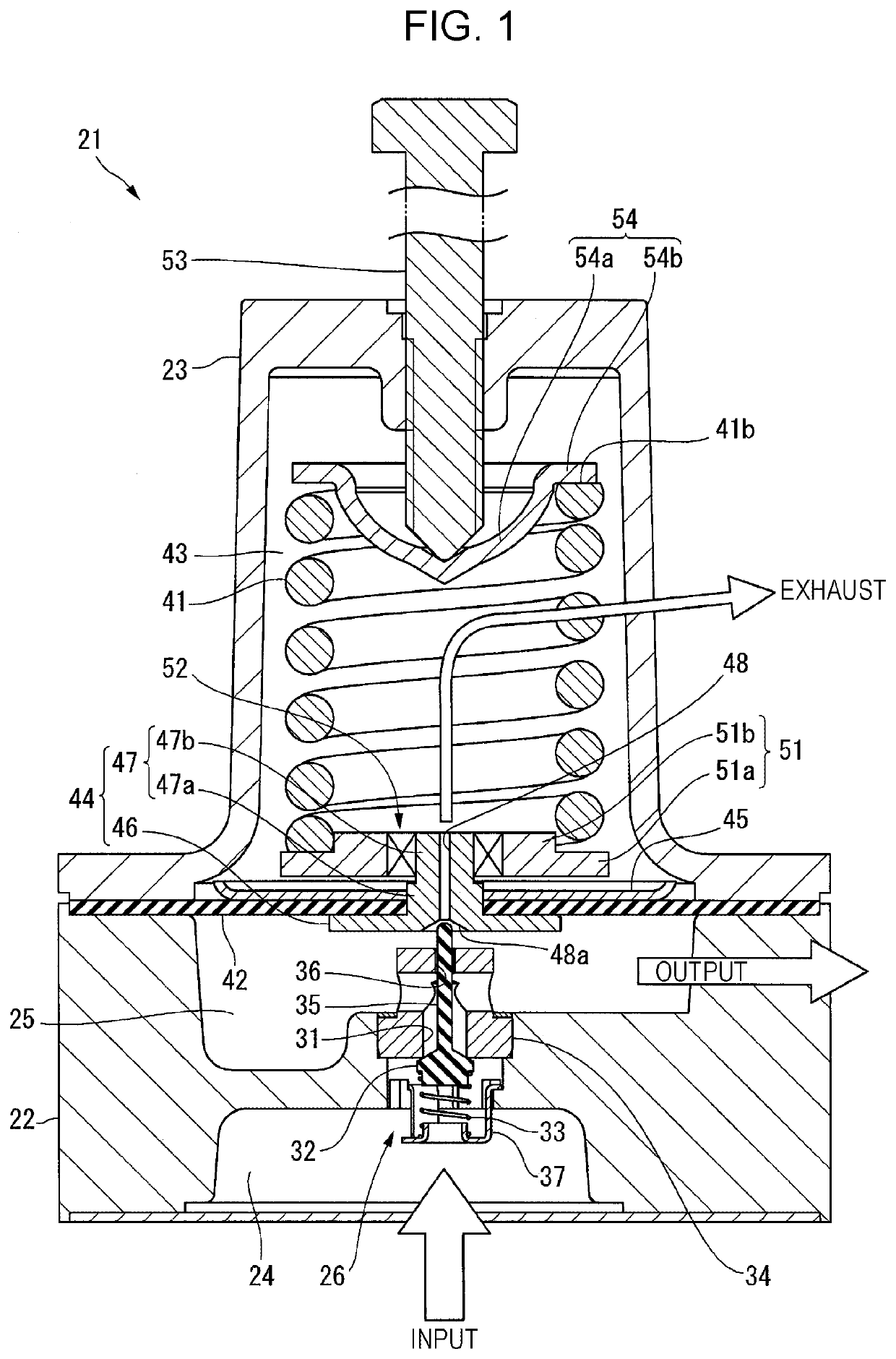
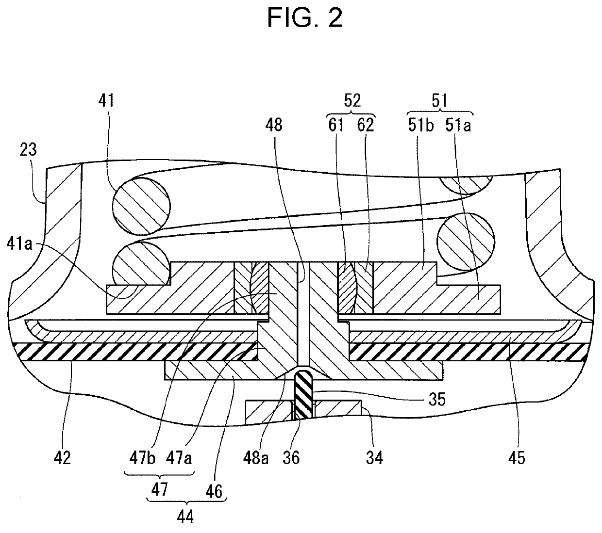
[0027]According to the present disclosure, the bearing allows the spring receiving member to move relative to the valve seat. Therefore, the valve seat is less affected by the above-described three phenomena generating when the compression coil spring is compressed or extended, i.e., the inclination of the end surface (first phenomenon), non-uniformity of the spring forces (second phenomenon), and the occurrence of torque due to the twisting (i.e., the third phenomenon).
[0028]As a result, the present disclosure can provide the air pressure control device which is less affected by behaviors of the compression coil spring when it is compressed or extended, and in which the valve seat supported by the diaphragm is displaced correctly and an exhaust leak does not occur.
[0029]Furthermore, in the adjustment valve according to the present disclosure, control of a valve opening degree is performed by the valve positioner including the air pressure control device that is less affected by the behaviors of the compression coil spring, and that is free from the exhaust leak and the failure of pressure adjustment. As a result, the highly-reliable adjustment valve can be obtained which is able to control the opening degree with high accuracy, to ensure a smaller loss of energy, and not to cause a malfunction of the adjustment valve.

Problems solved by technology

The exhaust leak becomes a factor of not only making an output pressure unstable, but also bringing about loss of energy.
Another problem is that exhaust sounds are noisy.
In addition, when wears of the contact portions of the pin 11 and the valve seat 12 are progressed, the pressure reducing valve may come into a state in which pressure adjustment is failed, thus causing an adjustment valve to malfunction (for example, not to operate or to operate slowly), and giving influences on a variety of apparatuses connected in subsequent stages.
Furthermore, the above-described friction force is greatly changed depending on a position of the pressure adjusting bolt 18 and an amount of compression of the compression coil spring 15, thereby making the contact state of the pressure adjusting bolt 18 unstable and increasing the torque given to the pressure adjusting bolt 18.
Thus, a difficulty resides in solving the problems attributable to the above-described three phenomena by utilizing the inclination and rotation of the upper seat 17.
However, using those guides is practically impossible for the reasons of an increase in operating force due to frictional resistances of the guides, wears of the guides, and scoring of sliding portions.

Method used


Image

  • Air pressure control device and adjustment valve
  • Air pressure control device and adjustment valve
  • Air pressure control device and adjustment valve

Examples


first embodiment

[0038]An air pressure control device according to a first embodiment of the present disclosure will be described in detail below with reference to FIGS. 1 and 2. This embodiment represents an example in which the present disclosure is applied to a pressure reducing valve that is an air pressure control device with the simplest configuration.

[0039]A pressure reducing valve 21 serving as an air pressure control device, illustrated in FIG. 1, is used to reduce the pressure of high-pressure air to a predetermined level, and to supply the air under the predetermined pressure to an actuator (not illustrated).

[0040]The pressure reducing valve 21 includes a first housing 22 positioned at the lower side in FIG. 1, and a second housing 23 mounted to the first housing 22. For the sake of convenience, the following description is made on an assumption that the lower side in FIG. 1 is called the one end side of the pressure reducing valve 21, and that the upper side in FIG. 1 is called the oppos...

second embodiment

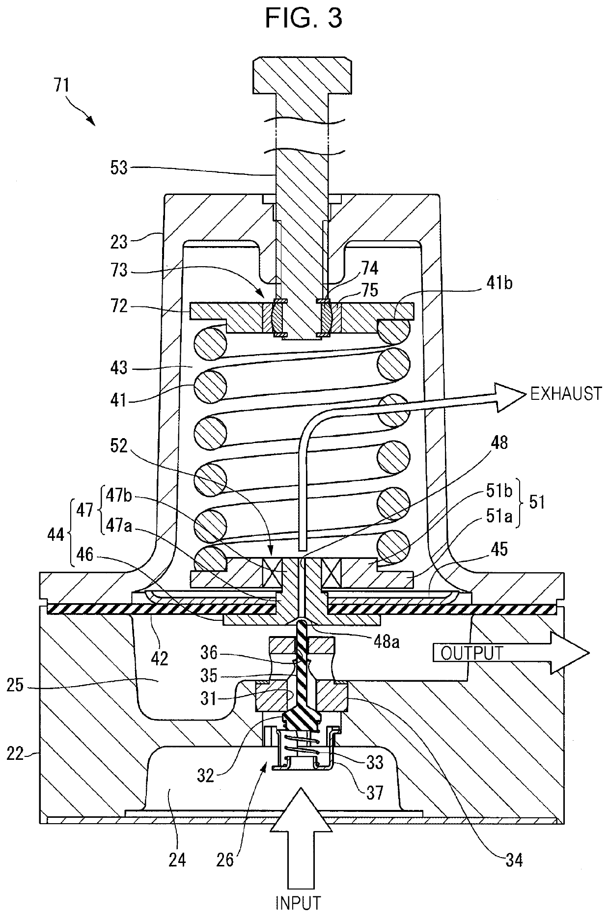
[0062]As illustrated in FIG. 3, the bearing may be further disposed in a portion supporting the opposite end of the main spring. In FIG. 3, the same or equivalent members as or to those described with reference to FIGS. 1 and 2 are denoted by the same reference signs, and detailed description of those members is omitted as appropriate.

[0063]In a pressure reducing valve 71 illustrated in FIG. 3, a bearing 73 is interposed between the pressure adjusting bolt 53 and an upper seat 72.

[0064]The bearing 73 is a spherical-surface slide bearing including an inner ring 74 and an outer ring 75 over which the inner ring 74 is fitted. The inner ring 74 is attached to the pressure adjusting bolt 53 in such a state that movement of the inner ring 74 in the axial direction of the pressure adjusting bolt 53 is restricted while the inner ring 74 is allowed to rotate. The outer ring 75 is fixedly fitted in an axial center portion of the upper seat 72. The upper seat 72 in this embodiment is in the fo...


PUM


Abstract

An air pressure control device includes first and second housings, a diaphragm partitioning an inner space of the housings into a first air chamber (one air chamber) and a second air chamber (the other air chamber), a valve seat supported by the diaphragm, a valve member arranged in the first air chamber and closing or opening a through-hole in the valve seat, a pressure adjusting mechanism (including a pressure adjusting bolt and an upper seat) that adjusts a force applied to the diaphragm from a side including the second air chamber, and a main spring (compression coil spring) disposed in the second air chamber and applying a spring force to a lower seat (spring receiving member) disposed on the valve seat. A bearing is interposed between the valve seat and the lower seat.

Description

CROSS-REFERENCE TO RELATED APPLICATIONS[0001]The present application is based on and claims priority to Japanese Application No. 2017-081882, filed Apr. 18, 2017, the entire contents of which are incorporated herein by reference.BACKGROUND[0002]1. Field[0003]The present disclosure relates to an air pressure control device including a valve seat supported by a diaphragm, and a compression coil spring for biasing the valve seat. The present invention further relates to an adjustment valve equipped with the air pressure control device.[0004]2. Description of the Related Art[0005]As known in the related art, an air pressure apparatus for driving an actuator by air pressure includes an air pressure control device to control an operation of the actuator. That type of air pressure control device has a mechanism of reducing the pressure of air supplied from an air pressure supply source, as disclosed in Japanese Unexamined Utility Model Registration Application Publication No. 7-8604, for e...

Claims


Application Information

Patent Timeline
Patent Type & Authority Patents(United States)
IPC IPC(8): G05D16/06
CPCG05D16/0663G05D16/0669G05D16/0636Y10T137/7794F16K31/1262F15B13/025F15B2211/522F16K17/06
Inventor INOUE, KAZUHISA
Owner YAMATAKE HONEYWELL CO LTD
Learn More